| CPC C21D 10/005 (2013.01) [F01D 5/286 (2013.01); G01N 2291/0234 (2013.01)] | 6 Claims |

|
1. A device for peening by coupling a laser shock wave and an ultrasonic shock wave in real time, the device comprising a synchronization device, a laser device, two ultrasonic shock devices, a working platform and a control system, wherein
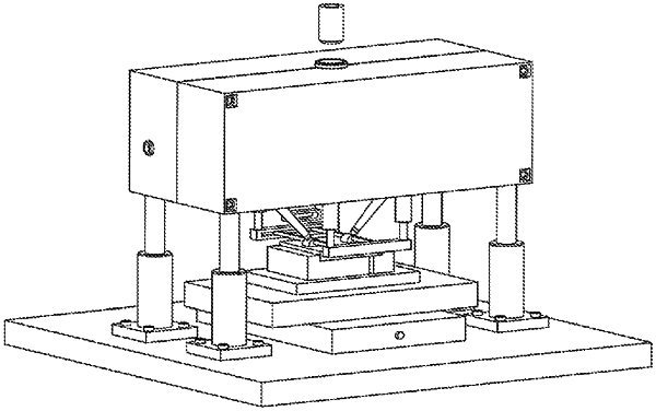
the working platform comprises an upper casing, first hydraulic cylinders, second hydraulic cylinders, limiting slide rails, and a base, wherein a horizontally movable workpiece is clamped above the base, the upper casing is supported above the base through the second hydraulic cylinders; the two supporting beams are respectively connected to the limiting slide rails, and are capable of sliding on the limiting slide rails; the limiting slide rails are provided under the upper casing, the first hydraulic cylinders are provided between the limiting slide rails and the upper casing; the two supporting beams are respectively provided with two transmission piles; the two ultrasonic shock devices are provided in the upper casing; the two ultrasonic shock devices are connected through the synchronization device, the synchronization device is configured to synchronize movement and rotation of the two ultrasonic shock devices; the laser device is configured to generate a laser beam to pass through the upper casing and irradiate a surface of the workpiece; and the control system controls the laser device to lag behind the two ultrasonic shock devices to perform a laser shock, so as to couple the laser shock wave and the ultrasonic shock wave in real time;
the synchronization device comprises a driving device, two racks, two first sliding devices, two second sliding devices, two hydraulic oscillating cylinders, and a hydraulic system, wherein the two first sliding devices are arranged in the upper casing; the two first sliding devices are slidably provided with the two hydraulic oscillating cylinders, respectively; output shafts of the two hydraulic oscillating cylinders are connected to the two ultrasonic shock devices, respectively; the hydraulic system is configured to control the two hydraulic oscillating cylinders to synchronously rotate; the two second sliding devices are arranged in the upper casing; the two second sliding devices are slidably provided thereon with the two racks, respectively; wherein each of the two first sliding devices comprises a first guide rail and a ball slider, and the ball slider is provided on the first guide rail; one of the two second sliding devices comprises an upper second slide rail and upper pulleys, and the other one of the two second sliding devices comprises a lower second slide rail and lower pulleys, the upper pulleys are provided on the upper second slide rail, and the lower pulleys are provided on the lower second slide rail;
the driving device comprises a motor and a motor shaft, and an external gear, and the external gear is provided on the motor shaft; the external gear meshes with the two racks; bearings are provided in ends of the two racks, respectively; the output shafts of the two hydraulic oscillating cylinders respectively pass through the bearings, such that the two racks are synchronously moved to allow the two hydraulic oscillating cylinders to be synchronously moved; and
the two ultrasonic shock devices each comprises a shock head, a horn, and a transducer, wherein the transducer is connected to the output shafts of the two hydraulic oscillating cylinders; the horn is provided at a bottom of the transducer; a tail end of the horn is provided with the shock head; the shock head and a respective one of the two transmission piles are in contact through the first hydraulic cylinders; and the shock head is rotated around a center of the respective one of the two transmission piles through the synchronization device.
|