| CPC B01J 19/088 (2013.01) [B01J 19/2445 (2013.01); C01B 3/04 (2013.01); C01B 17/0495 (2013.01); H05H 1/2406 (2013.01); B01J 2219/00038 (2013.01); B01J 2219/0813 (2013.01); B01J 2219/0869 (2013.01); B01J 2219/0875 (2013.01); B01J 2219/0896 (2013.01); H05H 1/245 (2021.05); H05H 1/246 (2021.05)] | 22 Claims |
|
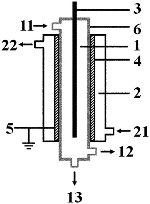
1. A low-temperature plasma reaction apparatus, the reaction apparatus comprising:
a first cavity provided with a first inlet and a first outlet, respectively;
a second cavity nested outside or inside the first cavity, and a second inlet and a second outlet are respectively arranged on the second cavity;
an inner electrode, at least part of the inner electrode extends into the first cavity;
an outer electrode forming at least part of a sidewall of the first cavity or being disposed on the sidewall of the first cavity in a surrounding manner; and
a barrier dielectric disposed between the inner electrode and the outer electrode such that a discharge region between the inner electrode and the outer electrode is separated by the barrier dielectric;
both the inner electrode and the outer electrode are solid electrodes, and the shapes of the inner electrode and the outer electrode are matched with each other to form an isodiametric structure;
the distance between an outer sidewall of the inner electrode and an inner sidewall of the outer electrode is denoted as L1, the thickness of the barrier dielectric is denoted as D1, L2=L1−D1, and the proportional relation between L2 and D1 is (0.1˜30):1;
wherein the first inlet is disposed at an upper portion of the first cavity, and the first outlet is disposed at a lower part and/or a bottom of the first cavity;
the first outlet includes a gas product outlet and a liquid product outlet, and the gas product outlet is disposed at the lower part of the first cavity, and the liquid product outlet is disposed at the bottom of the first cavity;
the gas product outlet is disposed below the discharge region, and a proportional relationship between a height H1 of the gas product outlet with respect to the bottom of the first cavity and a length L3 of the discharge region is: H1:L3=1:(30˜300).
|