| CPC H04R 25/305 (2013.01) [H04R 25/505 (2013.01); H04R 25/558 (2013.01); H04R 25/604 (2013.01); H04R 25/609 (2019.05); H04R 2225/55 (2013.01); H04R 2460/15 (2013.01)] | 21 Claims |

|
1. A hearing device, comprising:
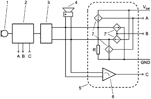
an input transducer (1);
a signal processor (2);
an amplifier (3), in particular a class D amplifier with an H-bridge;
a receiver (4),
a measurement bridge circuit (5) connected to the receiver (4) in parallel with the amplifier (3),
wherein the input transducer (1) is connected to the signal processor (2), the signal processor (2) is connected to the amplifier (3), and the amplifier (3) is connected to the receiver (4),
wherein a direct current or an alternating current is provided by a respective current steering digital-to-analogue converter (7, 7′),
wherein the measurement bridge circuit (5) is adapted to controllably supply the direct current or the alternating current to the receiver (4) and to measure a voltage at the receiver (4),
wherein the hearing device is operable in a normal mode and in a measurement mode,
wherein in the normal mode the amplifier (3) is enabled and provides an amplified output signal to the receiver (4),
wherein in the measurement mode the amplifier (3) is connected to the receiver and is disabled, and the measurement bridge circuit (5) supplies the direct current and/or alternating current to the receiver (4) and measures the voltage at the receiver (4),
wherein the current steering digital-to-analogue converter comprises a current source.
|