| CPC H03K 17/162 (2013.01) [H03K 17/002 (2013.01); H03K 17/6872 (2013.01)] | 18 Claims |
|
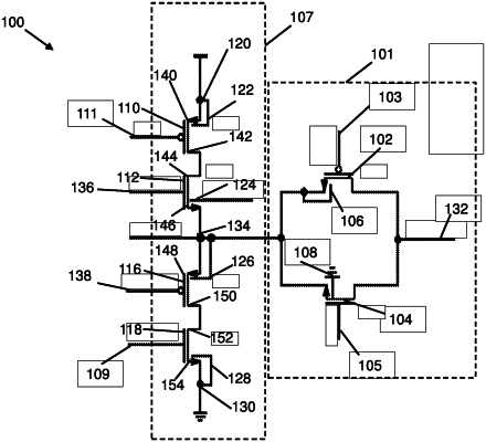
1. An analogue switch arrangement comprising:
an analogue switch comprising a first transistor in parallel with a second transistor between an input terminal and an output terminal, wherein a gate terminal of the first transistor is configured to receive a second control signal and wherein a gate terminal of the second transistor is configured to receive a first control signal, wherein the first control signal and the second control signal provide for control of the analogue switch between an on-state and an off-state;
an input transistor arrangement comprising a chain comprising a first control transistor having a first terminal coupled to a supply voltage terminal configured to receive a supply voltage and a second terminal coupled to a first terminal of a first voltage control transistor, a second terminal of the first voltage control transistor is coupled to a first terminal of a second voltage control transistor, a second terminal of the second voltage control transistor is coupled to a first terminal of a second control transistor and a second terminal of the second control transistor is coupled to a ground terminal configured to be coupled to a reference voltage;
wherein the input terminal is coupled to the second terminal of the first voltage control transistor and the first terminal of the second voltage control transistor; and
a gate of the first control transistor is configured to receive the second control signal, and a gate of the second control transistor is configured to receive the first control signal, wherein the first and second control transistors are configured to couple the first and second voltage control transistors to the supply voltage terminal and the ground terminal when the analogue switch is in the off-state; and
gate terminals of both the first and second voltage control transistors are configured to receive a voltage based on the voltage at the output terminal, and wherein the first and second voltage control transistors are configured to provide for control of the voltage applied at the input terminal based on the voltage at the output terminal when the analogue switch is in the off-state.
|