| CPC H01L 21/67781 (2013.01) [F27B 17/0025 (2013.01); H01L 21/67754 (2013.01); H01L 21/67757 (2013.01)] | 17 Claims |

|
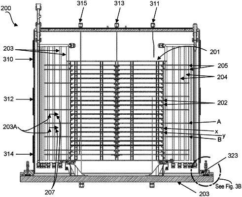
1. A batch processing oven, comprising:
a processing chamber;
a rack configured to be positioned in the processing chamber, wherein the rack is configured to support a plurality of substrates and a plurality of panels in a stacked manner such that (a) one or more substrates of the plurality of substrates are positioned between at least one pair of adjacent panels of the plurality panels, and (b) vertical gaps separate each substrate of the plurality of substrates from an adjacent substrate or panel on either side of the substrate
an inlet dissipater positioned on one side of the processing chamber, the inlet dissipater being configured to direct a gas into the processing chamber, wherein the inlet dissipater includes multiple inlet tubes extending in a lengthwise direction along an internal wall of the processing chamber, and wherein the multiple inlet tubes are arranged circumferentially to form a partial arc around the internal wall and each inlet tube of the multiple inlet tubes includes a plurality of inlet ports spaced apart from each other in the lengthwise direction;
an exhaust dissipater positioned on an opposite side of the processing chamber such that the rack is configured to be positioned between the inlet and exhaust dissipaters, the exhaust dissipator being configured to exhaust the gas from the processing chamber; and
one or more flow baffles positioned on an internal wall of the processing chamber, the one or more flow baffles being configured to restrict a flow of the gas around the rack positioned in the processing chamber.
|