| CPC H01H 1/14 (2013.01) [H01H 3/38 (2013.01); H01H 71/50 (2013.01); H01H 2235/01 (2013.01)] | 7 Claims |

|
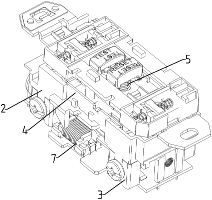
1. A ground fault circuit breaker protector for wrong wiring power-off protection, comprising two conductors fixedly mounted inside a shell (1), wherein one of the conductors is a power input end (2); and a line output end (3) is electrically connected to a load output end (4) through a transfer relay (7) and forms the other conductor;
the ground fault circuit breaker protector further includes a reset mechanism (5) and a movement arm (6); the movement arm (6) is downwards inclined; one end of the movement arm (6) is fixedly connected to the power input end (2), and the other end of the movement arm (6) contacts the line output end (3) and the load output end (4) from the bottom; the movement arm (6) is electrically connected to the line output end (3) and the load output end (4); the reset mechanism (5) is slidably arranged in the shell (1); the lower end of the reset mechanism (5) supports the bottom surface of the movement arm (6); and the transfer relay (7) is fixedly mounted on the shell (1);
wherein the reset mechanism (5) comprises a push rod (51), a sliding block (52), a buckle (53), and a trip mechanism (54); the sliding block (52) is slidably arranged in the shell (1); the push rod (51) slides in the shell(1); the push rod (51) is plugged into the sliding block (52); the buckle (53) is plugged into the sliding block (52) from the side surface of the sliding block (52); the buckle (53) locks the lower end part of the push rod (51); the trip mechanism(54) is clamped with the buckle (53); the trip mechanism (54) is located on one side of the buckle (53); and the sliding block (52) supports the bottom surface of the movement arm (6).
|