| CPC H01F 5/02 (2013.01) [H01F 27/266 (2013.01); H01F 41/071 (2016.01); H01F 2005/027 (2013.01)] | 16 Claims |

|
1. An inductor device comprising:
a rectangular prismatic magnetic core with eight vertexes and three pairs of opposite faces facing and parallel to one another defining an axis X, an axis Y, and an axis Z orthogonal to one another each perpendicular to one of said pairs of opposite faces and passing through the geometric center of the opposite faces;
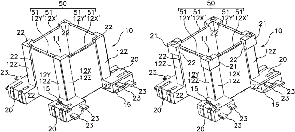
an electrically insulating support surrounding all but one of the opposite faces of the magnetic core and made of a single part with a rectangular prismatic cavity arranged around said magnetic core, said cavity completely housing the rectangular prismatic magnetic core and being accessible through an opening surrounded by a frame having four sides arranged opposite one another in pairs, said electrically insulating support being provided with:
two orthogonal winding up channels dimensioned to delimit respective two orthogonal windings (DX, DY) of conductive wire, said winding up channels being defined by winding supporting outer faces (12X, 12Y) each perpendicular to one of said axis X, Y, winding limiting edges perpendicular to the winding supporting outer faces (12X, 12Y), four additional winding supporting outer faces (12X′ and 12Y′) formed on said four sides of the frame and the winding limiting edges associated therewith;
winding supporting outer faces (12Z) perpendicular to one of said axis X and Y and configured to support a third winding (DZ) of conductive wire, orthogonal to the other two windings (DX, DY); and
four lower corner protuberances arranged on four vertexes of the magnetic core, including winding limiting edges perpendicular to the winding supporting outer faces),
said three windings being arranged orthogonal to one another wound around said magnetic core supported on said winding supporting faces (12X, 12Y, 12Z), confined between the winding limiting edges such that when a current circulates through the mentioned windings (DX, DY, DZ), an electromagnetic field with electromagnetic field vectors coaxial with the axes of each of the windings is generated,
wherein:
said frame is arranged flush with or above the level of the magnetic core,
said winding supporting outer faces (12Z) define four pilasters projecting from the four corners protuberances of the electrical insulating support, wherein an end of each pilaster also project from the frame forming steps determining said winding limiting edges;
said winding supporting outer faces extending from lower corner protuberances up to said pilaster end; and
said winding supporting outer faces (12Z), where the third winding (DZ) is wound, provide surfaces delimited on one side by said limiting edges of the lower corner protuberances; and
said third winding (DZ) is centered with respect to the orthogonal axes X and Y;
wherein said two orthogonal windings (DX, DY) and said third winding (DZ) are configured to in combination with the dimensions of the magnetic core define three isotropic orthogonal magnetic fields.
|