| CPC F04D 25/082 (2013.01) [A47L 5/22 (2013.01); A47L 9/22 (2013.01); F04D 29/403 (2013.01); F04D 29/444 (2013.01); F04D 29/5806 (2013.01); F04D 29/624 (2013.01); F04D 29/26 (2013.01)] | 20 Claims |

|
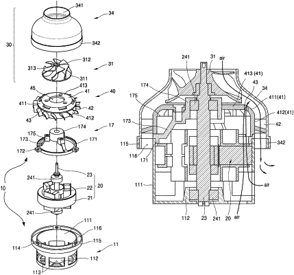
1. A fan motor for a vacuum cleaner, comprising:
a motor mount that accommodates a motor and defines a cooling flow path inlet at at least one of a lateral side or a lower side of the motor mount, the cooling flow path inlet being configured to receive air to reduce heat generated in the motor;
an impeller located vertically above the motor and configured to be rotated by the motor;
a diffuser located between the impeller and the motor mount; and
an impeller cover that is disposed vertically above the motor mount and covers the diffuser and the impeller, the impeller cover defining an air inlet at an upper portion thereof,
wherein the motor mount further defines an air discharge opening exposed to an outer space of the motor mount and configured to discharge air pressurized by the impeller to the outer space of the motor mount,
wherein the diffuser comprises a diffuser body that comprises a flat portion, the flat portion covering an inner space of the motor mount from the impeller,
wherein the diffuser body defines a cooling flow path outlet at a first portion of the diffuser adjacent to the impeller, the cooling flow path outlet being in fluid communication with the inner space of the motor mount and a first space defined between the impeller and the air discharge opening, and
wherein the cooling flow path outlet is configured to, based on a pressure difference between the inner space of the motor mount and the first space, discharge air from the inner space of the motor mount to the first space that has a lower pressure than the inner space of the motor mount.
|