| CPC F03D 13/10 (2016.05) [B66C 1/108 (2013.01); B66C 13/06 (2013.01); B66C 13/08 (2013.01); B66C 13/16 (2013.01); F05B 2230/61 (2013.01)] | 10 Claims |

|
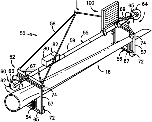
1. A lift system for a rotor blade of a wind turbine, the lift system comprising:
a lifting device comprising a structural frame body having a root end and a tip end, the root end supporting a root cradle, the tip end supporting a tip cradle, the root and tip cradles each comprising a profile that corresponds to at least one exterior surface of the rotor blade so as to receive and support at least a portion of the rotor blade, wherein, when the rotor blade is installed in the lifting device and lifted uptower, the rotor blade experiences an asymmetric loading; and,
a variable airflow assembly coupled to the tip end of the lifting device, the variable airflow assembly comprising at least one surface mounted to a frame member, the at least one surface moveable between a plurality of positions having varying resistances so as to counteract the asymmetric loading, the plurality of positions comprising, at least, a first position and a second position,
wherein the first position is an open position in which the at least one surface is rotated away from a plane of the frame member to allow airflow through the frame member, and wherein the second position is a closed position in which the at least one surface is generally parallel and in line with the plane of the frame member to limit the airflow through the frame member;
wherein the variable airflow assembly is moveably coupled to the tip end of the lifting device such that the variable airflow assembly can be moved to a hidden position with respect to the structural frame body to minimize an impact of the variable airflow assembly after the rotor blade has been installed uptower.
|