| CPC B65D 83/44 (2013.01) | 19 Claims |

|
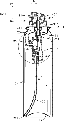
1. A valve mechanism for a high-pressure spray can, adapted to be mounted on a can body of the high-pressure spray can and being capable of providing communication between an interior and an exterior of the can body; the can body having an inner space and a can-mounting opening; the valve mechanism for the high-pressure spray can comprising:
a first reference direction being parallel to an axis of the can body and toward a top end of the can body;
a second reference direction being vertical to the first reference direction and pointing radially outward of the can body;
a third reference direction being parallel to the axis of the can body and toward a bottom end of the can body;
a valve assembly fixed on the can-mounting opening of the can body and sealing the can-mounting opening of the can body; the valve assembly having
a liquid product outlet located outside the can body;
a liquid product inlet located in the inner space of the can body; which selectively links the flow with the liquid product outlet; and
a switching base connected to a bottom end of the valve assembly and linking the flow with the valve assembly; the switching base having a main body having
a first passage having
a first end pointing toward the first reference direction;
a second end pointing toward the third reference direction;
a first linking opening formed on the first end of the first passage and linking the flow with the liquid product inlet; and
a first inclined inner wall surface located in a side of the first passage facing toward the second reference direction; the first inclined inner wall surface being inclined with respect to the axis of the can body and extending obliquely from the first end of the first passage to the second end of the first passage;
a first suction port linking the flow with the first passage; the first suction port linking the flow with the liquid product inlet via the first linking opening of the first passage;
a second passage having
a first end pointing toward the third reference direction;
a second end pointing toward the first reference direction;
a second linking opening formed on the first end of the second passage and linking the flow with the liquid product inlet; and
a second inclined inner wall surface located in a side of the second passage facing toward the second reference direction; the second inclined inner wall surface being inclined with respect to the axis of the can body and extending obliquely from the first end of the second passage to the second end of the second passage; and
a second suction port linking the flow with the second passage; the second suction port linking the flow with the liquid product inlet via the second linking opening of the second passage;
a first ball movably mounted in the first passage and selectively linking the first suction port and the liquid product inlet or blocking the first suction port and the liquid product inlet; and
a second ball movably mounted in the second passage and selectively linking the second suction port and the liquid product inlet or blocking the second suction port and the liquid product inlet;
wherein
when the can body is placed upright and the first reference direction is perpendicularly upward, the first ball slides down to a first opening position such that the first suction port is linking the flow with the liquid product inlet, and the second ball slides down to a second blocking position to block the second linking opening such that the second suction port and the liquid product inlet are blocked by the second ball;
when the can body is placed upside down and the first reference direction is perpendicularly downward, the second ball slides down to a second opening position such that the second suction port is linking the flow with the liquid product inlet, and the first ball slides down to a first blocking position to blocks the first linking opening such that the first suction port and the liquid product inlet are blocked by the first ball;
the first inclined inner wall surface extends to the first opening position and the first blocking position;
the second inclined inner wall surface extends to the second opening position and the second blocking position; and
when the can body is placed horizontally and the second reference direction is perpendicularly downward, the first ball abuts the first inclined inner wall surface and stays at a lower end of the first inclined inner wall surface such that the first suction port is linking the flow with the liquid product inlet, and the second ball abuts the second inclined inner wall surface and stays at a lower end of the second inclined inner wall surface such that the second suction port is linking the flow with the liquid product inlet; the first inclined inner wall surface and the second inclined inner wall surface are inclined to a different direction such that the first ball and the second ball slide down in co-motion to open the first suction port and the second suction port.
|