| CPC B63C 9/06 (2013.01) [B63C 9/03 (2013.01); B63J 2/02 (2013.01)] | 8 Claims |

|
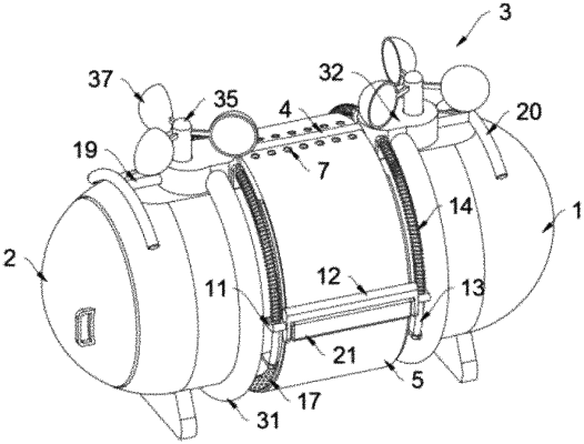
1. An aerogel heat preservation rescue cabin for ships, comprising a cabin body, wherein a cabin door (2) is arranged at one side of the cabin body (1); two water pumping devices (3) are symmetrically sleeved outside the cabin body (1) near two sides; a same straight pipe (4) is connected between the two water pumping devices (3); strip-shaped water outlet holes (23) are formed at front and rear sides of the straight pipe (4) in a penetrating manner; a heat insulation plate (5) is sleeved at a position, corresponding to the straight pipe (4), of the cabin body (1), and is hollow; two ends of the heat insulation plate (5) are respectively communicated with the water outlet holes (23) at the front and rear sides of the straight pipe (4); a plurality of drainage holes (6) are formed in an inner wall, opposite to the cabin body (1), of the heat insulation plate (5) in a penetrating manner; a plurality of evaporation holes (7) are formed at positions, near the two ends, of a top of the heat insulation plate (5) in a penetrating manner;
each of the two water pumping devices (3) comprises an arc-shaped pipe (31) which is fixedly sleeved on the cabin body (1); two ends of the arc-shaped pipe (31) are connected to a same water storage box (32); the water storage box (32) is fixedly connected to a top of the cabin body (1); the two ends of the arc-shaped pipe (31) are respectively inserted at front and rear sides of the water storage box (32) in a penetrating manner; one of the sides, close to the straight pipe (4), of the water storage box (32) is communicated with the straight pipe (4); water inlet holes (28) are formed in opposite sides of the two arc-shaped pipes (31) in a penetrating manner, and are close to bottoms of the arc-shaped pipes (31); annular plates (33) are rotatably arranged in the arc-shaped pipes (31); a plurality of water taking tanks (34) are fixedly connected to one side, close to the water inlet hole (28), of each of the annular plate (33); the water taking tanks (34) are matched with the arc-shaped pipes (31); a strip-shaped through hole (27) is formed in one side, far away from the annular plate (33), of each of the water taking tanks (34); teeth are uniformly arranged at an other side of the annular plate (33); a rotating shaft (35) is rotatably inserted in a top of the water storage box (32) in a penetrating manner; the rotating shaft (35) is located at one side where the teeth of the annular plate are located; a gear (36) is fixedly sleeved at a position, close to a bottom end, of the rotating shaft (35); the gear (36) is meshed with the teeth; a plurality of connecting rods are fixedly connected to a position, close to a top, of the rotating shaft (35); and wind cups (37) are fixedly connected to free ends of the connecting rods.
|