| CPC B62D 55/088 (2013.01) [B62D 55/06 (2013.01); B62D 55/125 (2013.01); B62D 55/244 (2013.01)] | 8 Claims |
|
1. A power machine, comprising:
a machine frame;
a track assembly coupled to the machine frame, the track assembly comprising:
a track frame;
a track supported by the track frame and configured to be driven around the track frame, the track having protruding teeth;
a drive motor assembly carried by the track frame, the drive motor assembly having a first portion fixedly attached to the track frame and a second portion coupled to and configured to rotate relative to the first portion;
a sprocket coupled to the second portion of the drive motor assembly and configured to rotate with the second portion, the sprocket having a plurality of sprocket teeth configured to engage the track;
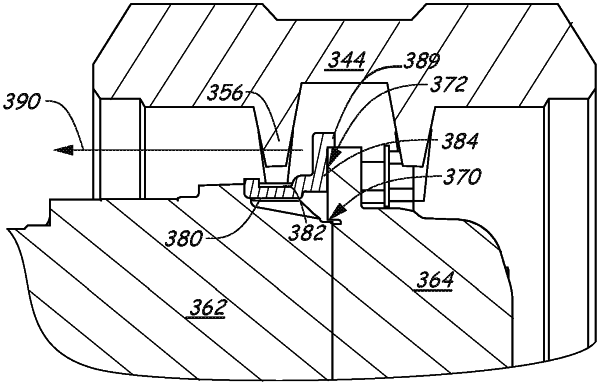
a one-piece shield attached to the first portion of the drive motor assembly, the one-piece shield comprising:
a first surface that is positioned against a surface of the first portion of the drive motor assembly to provide a sealing surface against the first portion;
a second surface configured to be positioned beneath the track when the shield is secured to the first portion of the drive motor assembly; and
a vertical wall adjacent the second surface and configured to be positioned proximal to the second portion of the drive motor assembly when the shield is secured to the first portion, the second surface extending from the vertical wall such that the second surface is positioned between the protruding teeth of the track and the drive motor assembly, a gap being formed between the vertical wall and the second portion of the drive motor assembly to allow the second portion to move relative to the vertical wall, the vertical wall and the second surface configured to urge material away from a critical path formed by a parting line between the first and second portions of the drive motor assembly.
|