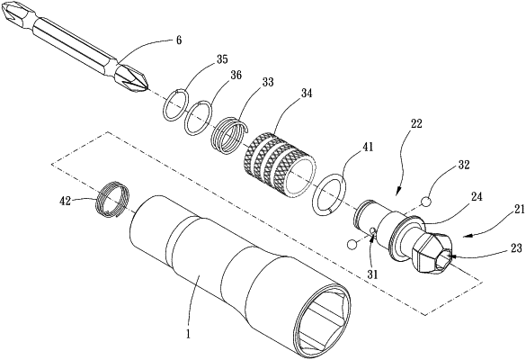
| CPC B25B 23/0035 (2013.01) [B25B 23/0014 (2013.01); B25B 21/00 (2013.01)] | 10 Claims |

|
1. A tool joint, including:
a main body, including a connecting channel and an assembling space which is in communication with the connecting channel along a first direction;
a swingable member, including a head portion, a connecting rod and an insertion hole, the connecting rod being connected with the head portion, the head portion being polygonal ball shaped, the head portion being received and movable in the assembling space so that the connecting rod is swingable relative to the main body, the insertion hole being disposed through the head portion and the connecting rod, the insertion hole including a first end and a second end opposite to each other, the second end being in communication with the connecting channel, wherein the tool joint further comprises a driving rod, and the first end being configured for insertion of the driving rod which is movable between a first position where the driving rod is non-protrusive beyond the second end and a second position where the driving rod is protrusive beyond the second end and projects within the connecting channel, the connecting channel being configured to block the driving rod in a direction perpendicular to the first direction, the insertion hole being non-circular; and
a locking structure, including at least one positioning hole, at least one positioning member, a first elastic member and a sleeve, the at least one positioning hole being disposed through the connecting rod and laterally in communication with the insertion hole, the at least one positioning member being movably received within the at least one positioning hole, the sleeve being disposed around the connecting rod and being movable between a locking position and a release position, wherein when the sleeve is located in the locking position, a first rib portion of the sleeve urges the at least one positioning member to be within the insertion hole so as to position the driving rod, when the sleeve is located in the release position, a receiving room of the sleeve receives part of the at least one positioning member so that the at least one positioning member is out of the insertion hole to release the driving rod, and wherein the first elastic member is disposed between the sleeve and the connecting rod to biases the sleeve toward the locking position.
|