| CPC A61F 2/4684 (2013.01) [A61B 17/1764 (2013.01); A61F 2/3859 (2013.01); A61B 17/155 (2013.01)] | 15 Claims |

|
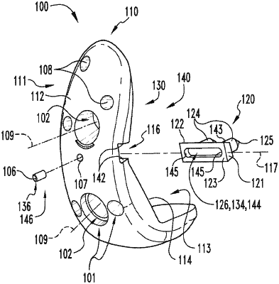
1. An orthopedic trial component configured to provisionally replace a portion of a bone of a joint, the orthopedic trial component comprising:
a body portion comprising:
an outward-facing side defining an articular surface for the joint;
an inward-facing side defining a bone-facing surface configured to abut a resection surface of the bone;
a slide channel formed in the inward-facing side of the body portion, wherein the slide channel extends along a slide axis, and is defined in part by an opening in the bone-facing surface; and
at least one drill guide extending from the articular surface to the bone-facing surface in a predetermined orientation relative to the body portion;
a slider body arranged and configured to be at least partially positioned within the slide channel, the slider body being arranged and configured to be slidably moveable with the slide channel along the slide axis, at least a portion of the slider body extending through the opening formed in the bone-facing surface to contact the resection surface of the bone in use;
a pin arranged and configured to interact with a channel formed in a rear surface of the slider body to selectively prevent movement of the slider body along the slide axis; and
a limiting mechanism configured to provide the slider body with a limited range of movement along the slide axis, wherein the limiting mechanism comprises a pair of end walls delimiting the channel, and wherein each of the end walls is configured to contact the pin to define a corresponding terminal position for the limited range of movement.
|