| CPC A63B 71/0686 (2013.01) [A63B 63/083 (2013.01); A63B 71/0669 (2013.01); G07C 1/22 (2013.01); G07C 1/28 (2013.01); A63B 2220/17 (2013.01); A63B 2220/62 (2013.01); A63B 2220/833 (2013.01)] | 17 Claims |

|
1. An auxiliary timing device [ for use with a scoreboard having a scoreboard controller and one or more audible or visual alarms, the auxiliary timing device ] comprising:
[ a plurality of control signals received from one or more signal inputs, said control signals selected from one or more inbound start signals, one or more shot clock start signals, one or more five-second violation signals, one or more ten-second violation signals, one or more ten-second reset signals, or combinations thereof; ]
a plurality of control signals;
wherein the auxiliary timing device is configured for use in a basketball game;
wherein the basketball game is further defined with one or more officials and a scoreboard;
wherein the scoreboard is further defined with a scoreboard controller, a game clock, a shot clock, and a shot clock start signal;
wherein the scoreboard controller is further defined with an audible alarm;
wherein the auxiliary timing device is configured for use with the scoreboard;
wherein the auxiliary timing device is a supplemental timing device;
wherein the five-second timing device, the ten-second timing device,
wherein the auxiliary timing device operates a ten-second timing device;
wherein the auxiliary timing device generates an alarm signal should the five-second timing device expire;
wherein the auxiliary timing device generates an alarm signal should the ten-second timing device expire;
wherein the auxiliary timing device is further configured for use with an external power source;
wherein each of the one or more time lapse displays are identical;
wherein each of the one or more time lapse displays present identical images;
wherein each of the one or more time lapse displays attaches to an existing scoreboard;
wherein the one or more time lapse displays are further configured for use with a computer;
wherein the plurality of control signals comprises an inbound start signal, a five-second violation signal, a ten-second violation signal, the shot clock start signal, and a ten-second reset signal;
wherein each of the plurality of control signals is an electrical connection that coordinates the operation o f the auxiliary timing device;
wherein each of the plurality of control signals is presented as a voltage;
wherein the five-second timing device is an electrical circuit;
wherein the five-second timing device is a timing circuit configured to use as a countdown timer;
wherein the five-second timing device is present to count down a five-second interval;
wherein the ten-second timing device is an electrical circuit;
wherein the ten-second timing device a timing circuit configured for use as a countdown timer;
wherein the ten-second timing device is present to count down a ten-second interval;
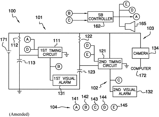
wherein the five-second timing device comprises a first timing circuit, a first resistor, and a first capacitor;
wherein the first timing circuit, the first resistor, and the first capacitor are electrically interconnected;
wherein the first timing circuit receives the inbound start signal and the shot clock start signal as inputs;
wherein the first timing circuit generates the five-second violation signal;
wherein the first timing circuit is an electrical circuit;
wherein the first timing circuit is an analog circuit;
wherein the first timing circuit measures five-second intervals;
wherein the value of the first resistor is measured in Ohms;
wherein the value of the first capacitor is measured in Farads;
wherein the first capacitor is a two lead electrical device that stores an electric charge;
wherein the first resistor and the first capacitor are connected in a series circuit;
wherein the first timing circuit is electrically connected to the first capacitor;
wherein the time interval generated by the first timing circuit is a known function of the combination the value in Ohms of the first resistor and the value in Farads of the first capacitor;
wherein the ten-second timing device comprises a second timing circuit, a second resistor, and a second capacitor;
wherein the second timing circuit, the second resistor, and the second capacitor are electrically interconnected;
wherein the second timing circuit receives the shot clock start signal and the ten-second reset signal as inputs;
wherein the second timing circuit generates the ten-second violation signal;
wherein the second timing circuit is an electrical circuit;
wherein the second timing circuit is an analog circuit;
wherein the second timing circuit measures ten-second intervals;
wherein the value of the second resistor is measured on Ohms;
wherein the value of the second capacitor is measured in Farads;
wherein the second capacitor is a two lead electrical device that store an electric charge;
wherein the second resistor and the second capacitor are connected in a series circuit;
wherein the second timing circuit is electrically connected to the second capacitor;
wherein the time interval generated by the second timing circuit is a known function of the combination the value in Ohms or the second resistor and the value in Farads of the second capacitor;
wherein each of the one or more time lapse displays comprises a first visual alarm, a second visual alarm, and an image sensor;
wherein the first visual alarm, the second visual alarm, and the image sensor attach to the scoreboard;
wherein the one or more time lapse displays receive the inbound start signal, the shot clock start signal, and the ten-second reset signal as inputs;
wherein the first visual alarm receives the five-second violation signal as an input;
wherein the second visual alarm receives the ten-second violation signal as an input.
|