| CPC H01F 13/006 (2013.01) [H01F 7/064 (2013.01); H03K 17/6871 (2013.01)] | 19 Claims |

|
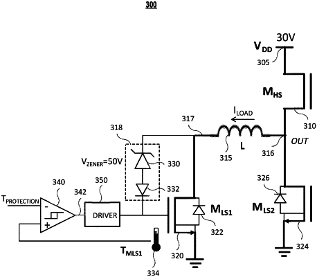
1. A discharge circuit for demagnetizing an inductive load, comprising:
a first switch having a first terminal coupled to one end of the inductive load;
a voltage regulator coupled between a control terminal of the first switch and the one end of the inductive load, the voltage regulator prevents current passing through when a voltage across the voltage regulator is less than a predetermined value;
a second switch coupled to another end of the inductive load, upon being switched on, the second switch grounds the another end of the inductive load such that a voltage at the one end of the inductive load reaches or is above the predetermined value;
a first temperature sensor that generates a sensed temperature signal based on a temperature of at least one component of the discharge circuit;
a comparing circuit that receives a reference temperature signal representing a predetermined temperature and the sensed temperature signal and generates an output with respect to a comparison between the reference temperature signal and the sensed temperature signal; and
a driver that receives the output from the comparing circuit and generates a driver output to the control terminal of the first switch, responsive to the output from the comparing circuit indicating that the temperature of the at least one component of the discharge circuit is above the predetermined temperature, the driver output switches on the first switch and causes the voltage across the voltage regulator below the predetermined value.
|