| CPC G06F 3/04166 (2019.05) [G06F 3/046 (2013.01); G06F 3/0412 (2013.01); G06F 3/0446 (2019.05); G06F 2203/04111 (2013.01)] | 3 Claims |

|
1. A display apparatus comprising:
a substrate;
a plurality of pixel electrodes;
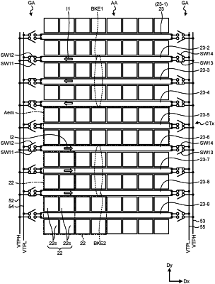
a plurality of detection electrodes arranged in a matrix in a display area of the substrate;
a plurality of detection electrode lines coupled to the respective detection electrodes;
a plurality of first electrodes provided in the same layer as the detection electrodes or the detection electrode lines and extending in a first direction;
a plurality of switching elements coupled to the respective pixel electrodes;
a plurality of signal lines coupled to the switching elements and extending in a second direction crossing the first direction;
a coupling member provided in a peripheral area outside the display area and configured to couple ends of the first electrodes to each other; and
a drive circuit configured to output a first drive signal in a first sensing period in which an electromagnetic induction method is used, wherein
the detection electrode lines extend in the second direction,
the first electrodes are provided in the same layer as the detection electrode lines and cross the detection electrode lines in a plan view,
each of the detection electrode lines includes a first partial detection electrode line and a second partial detection electrode line, and
the first partial detection electrode line and the second partial detection electrode line are placed adjacent to each other in the second direction with a corresponding one of the first electrodes therebetween and are electrically coupled to each other via a bridge line provided in a different layer from the detection electrode lines.
|