| CPC G03B 17/563 (2013.01) [F16M 11/08 (2013.01); F16M 11/205 (2013.01); F16M 11/2057 (2013.01); F16M 11/2064 (2013.01); F16M 11/2071 (2013.01); F16M 13/04 (2013.01); F16M 2200/024 (2013.01); F16M 2200/041 (2013.01); F16M 2200/042 (2013.01)] | 16 Claims |
|
1. A stabilizer folding structure comprising:
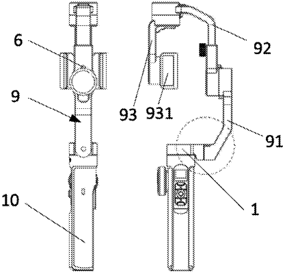
a motor base (1) pivotally connecting a rocker arm, said rocker arm comprising a heading arm, a cross roller arm and a tilting arm sequentially connected by a rotating motor;
an elastic member (2) for applying an elastic force for abutting the motor base (1) and the rocker arm;
a snap structure at a position where the motor base (1) abuts the rocker arm; in a first state and a second state, the snap structure is engaged to restrict relative rotation of the motor base (1) and the rocker arm;
in other states, the snap structure is disengaged such that the motor base (1) and the rocker arm are relatively rotatable;
wherein the motor base (1) and the rocker arm abut against each other, and the snap structure is disposed on an abutting surface;
a rotating shaft (3) having two ends, the two ends are respectively connected to the motor base (1) and the rocker arm, wherein the motor base (1) and the rocker arm are rotatable about the rotating shaft (3),
a stop sleeve (4),
a first mounting slot is opened at a joint of the motor base (1) and the rocker arm (11);
one end of the rotating shaft (3) is fixedly mounted in a first mounting slot (11);
the stop sleeve (4) is fixedly disposed in the first mounting slot (11);
a positioning sleeve (5), and
a second mounting slot (911) is defined in the rocker arm and the motor base (1), and the other end of the rotating shaft (3) is rotatably connected to the second mounting slot (911),
wherein the positioning sleeve (5) is fixedly disposed in the second mounting slot (911), and one side of the positioning sleeve (5) abuts against an end surface of the stop sleeve (4) when the motor base (1) is rotatably connected with the rocker arm, and the snap structure disposed on an end surface of the positioning sleeve (5) and the stop sleeve (4);
a buckle is disposed on an end surface of the positioning sleeve (5) and a latching position is set at least two recesses (41) corresponding to the at least one wedge-shaped boss (51) on the end surface of the stop sleeve (4), wherein in the first state and the second state, the at least one wedge-shaped boss (51) is engaged in the recess (41), wherein in the other states, the at least one wedge-shaped boss (51) abuts against the end surface of the stop sleeve (4); and
a limiting structure disposed at a position where the rocker arm is coupled to the motor base (1) for providing the rocker arm a rotational path that rotates relative to the motor base (1).
|