| CPC G01R 1/07328 (2013.01) [G01R 1/06705 (2013.01); G01R 31/2886 (2013.01)] | 6 Claims |

|
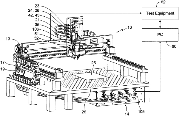
1. A probe assembly for use with a circuit board test apparatus that is capable of holding a unit under test (UUT), comprising:
a two pin probe portion having two spaced test probe mounting block assemblies;
first and second test probes mounted respectively in the mounting block assemblies, wherein the probe mounting block assemblies and the first and second test probes are both moveable in a controlled fashion linearly toward and away from each other;
motor encoder assemblies for moving the probe assembly in the X and Y directions, respectively, relative to the printed circuit board, including rotating the two pin probe portion with the test probes, wherein the motor encoder assemblies include first and second motors operable independently of each other, wherein the first motor rotates the two probes together around a single center line, maintaining the same orientation in the X Y plane during rotation thereof and wherein the second motor moves both of the test probes linearly toward and away from each other;
a motor encoder assembly for moving the probe assembly in the Z direction relative to the printed circuit board;
a camera for selecting first and second pin locations on the UUT, for the test probes;
a control assembly for calculating the distance between the selected first and second pin locations and for controlling the movement of the first and second test probes to the selected pin locations on the UUT;
wherein signals from the pin locations on the UUT are received by the test probes in contact therewith; and
a connection line for transmitting received signals from the selected pins to a test instrument for display of the received signals.
|