| CPC F16K 15/028 (2013.01) [E03C 1/1225 (2013.01); F16K 15/035 (2013.01); F16K 15/04 (2013.01); F16K 25/00 (2013.01); E03F 5/08 (2013.01)] | 19 Claims |

|
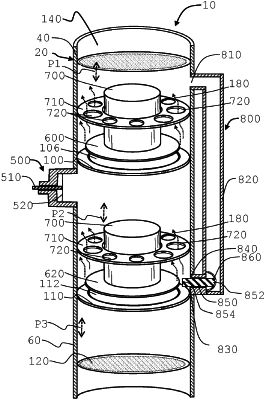
1. An apparatus to allow or stop an air flow into an enclosed environment or a piping system, comprising:
(a) a housing having an upper flow passage, a middle flow passage, a lower flow passage, wherein the upper flow passage is above the middle flow passage, wherein the middle flow passage is above the lower flow passage, wherein a first pressure exists in the upper flow passage, wherein a second pressure exists in the middle flow passage, wherein a third pressure exists in the lower flow passage;
(b) a first valve seat, wherein the first valve seat is between the upper flow passage and the middle flow passage, and wherein a at least one opening is formed on the first valve seat;
(c) a first sealing member, wherein the first sealing member is configured and dimensioned to substantially cover the at least one opening of the first valve seat, wherein the first sealing member can move upwardly and downwardly above the first valve seat;
(d) a second valve seat, wherein the second valve seat is between the middle flow passage and the lower flow passage, and wherein a at least one opening is formed on the second valve seat;
(e) a second sealing member, wherein the second sealing member is configured and dimensioned to substantially cover the at least one opening of the second valve seat, wherein the second sealing member can move upwardly and downwardly above the second valve seat;
(f) at least one locking mechanism configured to block or allow a movement of the first sealing member or the second sealing member;
(g) at least one carrier connected with the first sealing member; at least one carrier alignment guide; and wherein the at least one carrier is disposed through the at least one carrier alignment guide;
wherein the first sealing member moves away from the first valve seat when the second pressure is greater than the first pressure in a predetermined pressure difference;
wherein the second sealing member moves away from the second valve seat when the third pressure is greater than the second pressure in a predetermined pressure difference;
wherein the first pressure communicates with a system pressure in the enclosed environment or the piping system; and wherein the third pressure communicates with an ambient air pressure;
wherein a plurality of openings is formed through the at least one carrier alignment guide.
|