| CPC F16H 48/34 (2013.01) [F16H 48/24 (2013.01); F16D 2027/002 (2013.01); F16D 2300/18 (2013.01); F16H 2048/204 (2013.01); F16H 2048/346 (2013.01)] | 6 Claims |

|
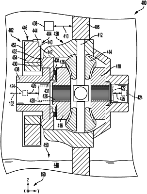
1. A locking differential system, comprising:
a driving gear;
a differential drive with an input part and two output parts, wherein the two output parts are drivingly connected to the input part and, relative to one another, have a differential effect;
a coupling effectively arranged between the driving gear and the differential drive, wherein, in a closed condition of the coupling, torque is transmitted from the driving gear to the differential drive and, in an open condition of the coupling, the transmission of torque is interrupted;
a controllable actuator for actuating the coupling, wherein the actuator comprises an electromagnet and an axially displaceable piston, and wherein the actuator is configured to generate a current signal representing a coil current of the electromagnet; and
a multi-sensor sub-assembly having two eddy current sensors coupled to a common microcontroller, wherein each eddy current sensor is configured to generate a sensor signal representing a first, engaged position or a second, disengaged position of the coupling, but with each of the two eddy current sensors switching between their respective indications at different physical positions;
wherein the two eddy current sensors include a first eddy current sensor with a first inductive coil and a second eddy current sensor with a second inductive coil, and wherein each of the first inductive coil and the second inductive coil is formed of coils stacked along a first axis; and
wherein the multi-sensor sub-assembly includes a first oscillator configured to activate the first inductive coil and a second oscillator configured to activate the second inductive coil, and wherein operation of the multi-sensor sub-assembly includes switching between activating the first inductive coil and the second inductive coil.
|