| CPC F15B 11/161 (2013.01) [B65F 3/04 (2013.01); F15B 2211/205 (2013.01); F15B 2211/20553 (2013.01); F15B 2211/6652 (2013.01)] | 18 Claims |

|
1. A refuse vehicle, comprising:
a chassis supporting a plurality of wheels;
a vehicle body supported by the chassis and defining a receptacle for storing refuse therein;
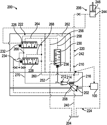
a variable displacement pump positioned within the vehicle body and configured to pump hydraulic fluid from a hydraulic fluid reservoir into a high pressure line of a hydraulic circuit;
a lifting system coupled to the vehicle body and movable relative to the receptacle, the lifting system including at least one actuator in fluid communication with the variable displacement pump, wherein the variable displacement pump delivers pressurized hydraulic fluid from the hydraulic fluid reservoir to the actuator through the high pressure line to adjust a position of the at least one actuator; and
a valve positioned downstream of the variable displacement pump and configured to selectively control hydraulic fluid flow between the variable displacement pump and the actuator, wherein in a first position, the valve restricts flow outward from the high pressure line and wherein in a second position, the valve directs hydraulic fluid from the high pressure line into a lower pressure line to reduce a hydraulic pressure within the high pressure line and adjust an output parameter of the variable displacement pump;
a first sensor positioned along the high pressure line and configured to monitor the hydraulic pressure within the high pressure line;
a second sensor configured to monitor an output flow rate from the variable displacement pump; and
a processor in communication with the first sensor and the second sensor, the processor being configured to control the valve to transition between the first position and the second position in response to determining that a product of the hydraulic pressure in the high pressure line and the output flow rate from the variable displacement pump exceeds a threshold value.
|