| CPC F02K 7/06 (2013.01) [F02C 5/11 (2013.01); F02C 5/12 (2013.01); F02K 7/08 (2013.01); F23R 7/00 (2013.01); F02K 7/10 (2013.01); F05D 2220/80 (2013.01)] | 15 Claims |

|
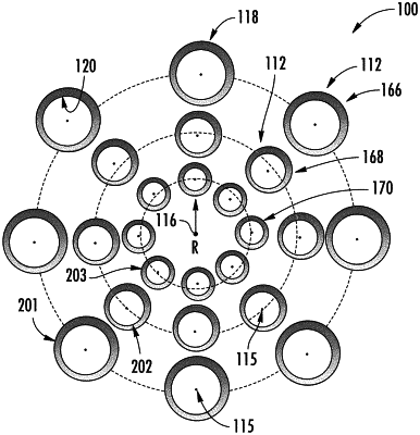
1. A rotating detonation combustion (RDC) system for a propulsion system, the rotating detonation combustion system defining a radial direction, a circumferential direction, and a longitudinal centerline, the rotating detonation combustion system comprising:
a plurality of combustors in adjacent arrangement along the circumferential direction, wherein each combustor defines a combustor centerline extended through each combustor, and wherein each combustor comprises an outer wall defining a combustion chamber and a combustion inlet, wherein each combustion chamber is defined by an annular gap and a combustion chamber length together defining a volume of each combustion chamber, and further wherein each combustor defines a plurality of nozzle assemblies each disposed at the combustion inlet in adjacent arrangement around each combustor centerline, and wherein a first array of combustors of the plurality of combustors includes combustors having combustion chambers defining a first volume and a second array of combustors of the plurality of combustors includes combustors having combustion chambers defining a second volume different from the first volume, wherein the combustors of the first array of combustors are in adjacent circumferential arrangement with one another a first radial distance from the longitudinal centerline, and the combustors of the second array of combustors are in adjacent circumferential arrangement with one another a second radial distance from the longitudinal centerline different from the first radial distance, and respective combustors in the first array of combustors are radially aligned in the radial direction with respective combustors in the second array of combustors,
wherein, in a lowest steady-state operating condition of the rotating detonation combustion system, fuel is delivered to each combustor in the first array of combustors and fuel is restricted from being delivered to the combustors in the second array of combustors such that each combustor in the first array of combustors is operated at the lowest steady-state operating condition and each combustor in the second array of combustors is not operated at the lowest steady-state operating condition, and at a highest steady-state operating condition of the rotating detonation combustion system, fuel is delivered to each combustor in the second array of combustors such that each combustor in the second array of combustors is operated at the highest steady-state operating condition, and
wherein the RDC system further defines a third array of combustors, each combustor of the third array of combustors being aligned along the radial direction with the respective combustors of the first array of combustors and the respective combustors of the second array of combustors, and wherein the combustors of the third array of combustors each define a third volume different from the first volume and from the second volume, wherein the third array of combustors is configured to produce a detonation cell width specific to an intermediate steady-state or transient operating condition of the RDC system, and wherein, in the lowest steady-state operating condition of the RDC system, fuel is restricted from being delivered to the combustors in the third array of combustors, and in the intermediate steady-state or a transient operating condition of the RDC system, fuel is delivered to each combustor in the third array of combustors such that each combustor in the third array of combustors is operating at the intermediate steady-state or transient operating condition.
|