| CPC F01D 17/165 (2013.01) [F01D 25/145 (2013.01); F05D 2220/40 (2013.01)] | 9 Claims |
|
1. A method of assembling a turbocharger having a vaned turbine nozzle, comprising the steps of:
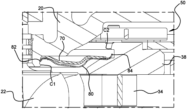
providing a rotor assembly comprising a center housing defining a central bore extending therethrough and having bearings housed within the bore, a shaft rotatably supported by the bearings and having a first end extending out from one end of the bore and an opposite second end extending out from an opposite end of the bore, a compressor wheel connected to the first end of the shaft, and a turbine wheel connected to the second end of the shaft, wherein the center housing defines a nose portion at said opposite end of the bore, the nose portion defining a radially outer peripheral surface and a first catch projecting radially outwardly from said radially outer peripheral surface;
providing a vane assembly comprising a generally annular nozzle ring having a first face and an opposite second face, and an array of circumferentially spaced vanes adjacent said first face of the nozzle ring, wherein the nozzle ring defines a radially inner peripheral surface and a second catch projecting radially inwardly from said radially inner peripheral surface adjacent said second face of the nozzle ring;
providing an annular heat shield having an inner periphery and an outer periphery;
forming a first snap fit between the inner periphery of the heat shield and the first catch on the nose of the center housing so as to form a captive connection of the heat shield to the center housing;
forming a second snap fit between the outer periphery of the heat shield and the second catch on the nozzle ring so as to form a captive connection of the vane assembly to the center housing, thereby forming a rotor-and-vane assembly comprising the rotor assembly coupled with the vane assembly; and
moving the rotor-and-vane assembly as a unit toward a turbine housing defining a receptacle, so as to move the turbine wheel into the receptacle in the turbine housing, and fastening the rotor-and-vane assembly to the turbine housing.
|