| CPC F01D 11/025 (2013.01) [F01D 9/04 (2013.01); F01D 11/005 (2013.01); F01D 11/08 (2013.01); F01D 25/246 (2013.01); F05D 2220/32 (2013.01); F05D 2230/60 (2013.01); F05D 2240/11 (2013.01)] | 18 Claims |

|
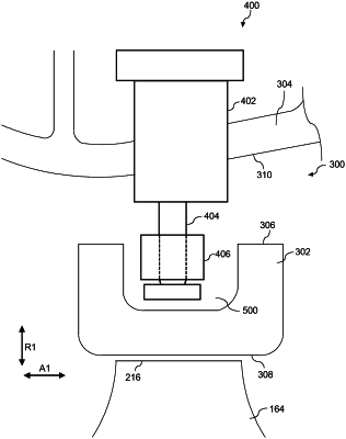
1. A shroud assembly defining an axial direction, a radial direction, and a circumferential direction, comprising;
a shroud support;
an annular shroud defining a radial centerline along the circumferential direction, the annular shroud comprising one or more retention features having a circumferential surface; and
one or more pins, each pin having an outer pin coupled to the shroud support and an inner pin disposed radially inward from the outer pin, the inner pin having a block thereon capable of radially translating along the inner pin, wherein the inner pin is offset from a radial center line of the outer pin,
wherein the block engages the circumferential surface of the one or more retention features for securing the annular shroud to the shroud support.
|