| CPC F01D 5/10 (2013.01) [F01D 25/164 (2013.01); F05D 2240/50 (2013.01); F05D 2250/14 (2013.01); F05D 2260/96 (2013.01)] | 19 Claims |

|
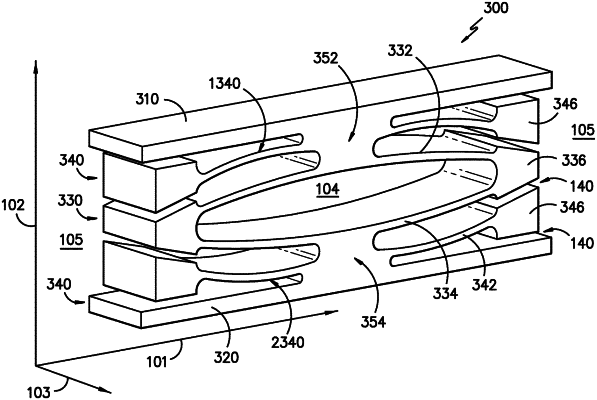
1. A damper system, the damper system comprising:
a first wall extended along a first direction;
a second wall extended along the first direction, wherein the first wall and the second wall are separated along a second direction perpendicular to the first direction;
an inner spring positioned between the first wall and the second wall along the second direction, wherein the inner spring comprises a first member and a second member each coupled together at a distal end along the first direction by an inner bumper, and wherein the first member, the second member, and the inner bumper form a cavity therebetween; and
an outer spring comprising:
a first outer spring positioned along the second direction between the first wall and the inner spring; and
a second outer spring positioned along the second direction between the second wall and the inner spring,
wherein the outer spring comprises a spring arm contoured along the second direction toward the inner spring, and
wherein the outer spring comprises an outer bumper positioned along the second direction between the inner bumper and the first wall or the second wall, and
wherein the inner bumper and the outer bumper are selectively couplable to one another based on a load applied to the damper system.
|
|
19. A system, the system comprising:
a rotor assembly mounted to a static structure via a bearing assembly, wherein the static structure and the bearing assembly are connected to one another at least by a damper element, wherein the damper element comprises:
a first wall extended along a first direction;
a second wall extended along the first direction, wherein the first wall and the second wall are separated along a second direction perpendicular to the first direction;
an inner spring positioned between the first wall and the second wall along the second direction, wherein the inner spring comprises a first member and a second member each coupled together at a distal end along the first direction by an inner bumper, wherein the first member and the second member are each contoured toward one another along the second direction, and wherein the first member, the second member, and the inner bumper form a cavity therebetween; and
an outer spring positioned along the second direction between the inner spring and the first wall or the second wall,
wherein the outer spring comprises a spring arm contoured along the second direction toward the inner spring, and
wherein the outer spring comprises an outer bumper positioned along the second direction between the inner bumper and the first wall or the second wall,
wherein the inner bumper and the outer bumper are selectively couplable to one another based on a load applied to the first wall or the second wall, and
wherein the first member comprises a perforation allowing fluid communication to the cavity at the inner spring.
|