| CPC E21B 47/135 (2020.05) [E21B 17/206 (2013.01); G02B 6/443 (2013.01); G02B 6/4463 (2013.01)] | 2 Claims |

|
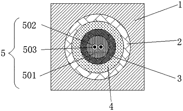
1. A manufacturing method of a logging encapsulated optical-fiber duct cable, the logging encapsulated optical-fiber duct cable comprising an external encapsulation layer (1), wherein at least one armor tube (2) is arranged in the encapsulation layer (1); an optical fiber protective tube (3) is arranged in each armor tube (2); a filling layer (4) is arranged in a space between the optical fiber protective tube (3) and the armor tube (2); an optical fiber (5) is arranged in the optical fiber protective tube (3); wherein the encapsulation layer (1) is further provided with reinforcing ribs (6) or an oil tube (7), and the reinforcing ribs (6) are not in contact with the armor tube (2); wherein the encapsulation layer (1) is made from thermoplastic vulcanizate (TPV) thermoplastic material; the optical fiber (5) comprises a high temperature coating (501); at least one core (503) is arranged in the high temperature coating (501); each core (503) is coated with a quartz cladding (502), and the high temperature coating (501) is selected from a high-temperature acrylate coating or a polyimide coating,
the manufacturing method comprising the following steps:
step 1: pavement of the optical fiber and formation of the protective tube: respectively placing a steel coil raw material for producing the optical fiber protective tube (3) and the wound optical fiber (5) on relative winding devices; guiding the start end of the steel coil raw material for producing the optical fiber protective tube (3) to sequentially pass through a steel tube initial forming device, an optical fiber winding device, a laser welding device, a nondestructive testing device, a steel tube drawing device and a traction device to produce the optical fiber protective tube (3); winding the optical fiber protective tube (3) by an optical fiber protective tube winding device;
step 2: formation of the filling layer:
when the filling layer (4) is formed by an aluminum tube, respectively placing an aluminum coil raw material for producing the filling layer (4) and the wound optical fiber protective tube (3) on relative winding devices; guiding the start end of the aluminum coil raw material for producing the filling layer (4) to sequentially pass through an aluminum tube initial forming device, an optical fiber protective tube winding device, a laser welding device, a tube diameter finishing device and a traction device to produce the aluminum tube; winding the aluminum tube by a winding device;
step 3: formation of the armor tube: placing a steel coil raw material for producing the armor tube (2) and the aluminum tube on relative winding devices; coating the filling layer (4) with the armor tube (2) by the devices in step 1; winding the filling layer coated with the armor tube by the winding device;
step 4: formation of the encapsulation layer: placing the armor tube (2) to be encapsulated on a relative winding device, guiding the start end of the armor tube (2) to sequentially pass through a straightening device, a preheating device, an encapsulation and extrusion device, a cooling device and a traction device to form the encapsulation layer (1); winding the encapsulated armor tube by the winding device.
|