| CPC C03B 17/04 (2013.01) | 13 Claims |

|
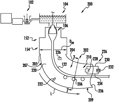
1. A glass tube manufacturing apparatus for manufacturing glass tubing, comprising:
a glass delivery tank with molten glass, the glass delivery tank having a bottom opening; a bell having an upper portion with an outer diameter located at the bottom opening;
a heating apparatus at least partially disposed around the bell forming a furnace, the heating apparatus including a heated portion disposed around the bell and a muffle portion that extends about a periphery of the glass tubing and is located below the heated portion;
a lower extended muffle structure that extends downwardly from the muffle portion, the lower extended muffle structure extending about the periphery of the glass tubing to manage convective airflow therethrough; and
a cover plate that covers a bottom opening of the lower extended muffle structure, the cover plate having an opening through which the glass tubing passes, the opening of the cover plate having a smaller dimension than the bottom opening of the lower extended muffle structure,
wherein the glass tube manufacturing apparatus is configured for the glass tubing to move vertically from the bell through the muffle portion, and configured for the glass tubing to move from a vertical orientation to a horizontal orientation, and
wherein the lower extended muffle structure includes a vertically extending portion and a horizontally extending portion both extending about the periphery of the glass tubing as the glass tubing moves from a vertical orientation to a horizontal orientation, the vertically extending portion disposed between the muffle portion and the horizontally extending portion, the lower extended muffle structure supported by a support structure comprising a support supporting the lower extended muffle structure around the glass tubing, the lower extended muffle structure having a circular cross-section and having a maximum distance from the glass tubing of no more than a preselected distance along an entire length of the lower extended muffle structure.
|