| CPC B60H 1/02 (2013.01) [B60H 1/034 (2013.01); B60H 1/143 (2013.01); E02F 9/0866 (2013.01); E02F 9/16 (2013.01); F15B 21/0423 (2019.01); H02K 9/19 (2013.01); B60N 2/56 (2013.01); E02F 3/961 (2013.01); E02F 9/2221 (2013.01)] | 20 Claims |

|
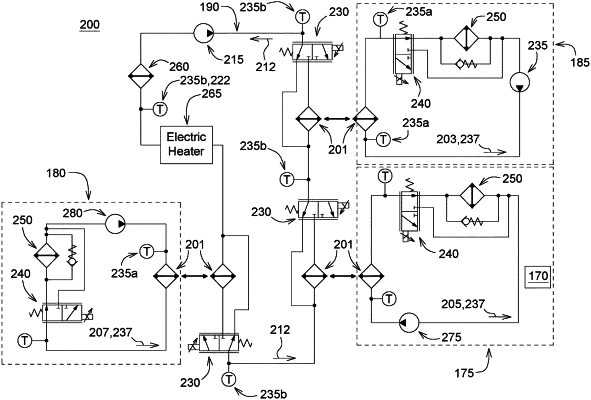
1. A work machine comprising:
a prime mover, an electric motor supplying at least a portion of power of the prime mover;
an electric motor fluid circuit adapted to remove waste heat from the electric motor;
a transmission fluid circuit adapted to lubricate a moving part of a transmission powered by the prime mover, the transmission fluid circuit having waste heat;
a hydraulic circuit adapted to transmit power from the prime mover to a moving component of the work machine, the hydraulic circuit having waste heat;
a cooling circuit circulating a cooling medium, the cooling circuit absorbing the waste heat from one or more of the electric motor fluid circuit, the transmission fluid circuit, and the hydraulic circuit; and
a controller adapted to control diversion of at least a portion of the waste heat from the cooling circuit to at least a portion of a cab of the work machine.
|