| CPC B60C 15/04 (2013.01) [B60C 15/0632 (2013.01); B60C 2015/044 (2013.01); B60C 2200/06 (2013.01)] | 14 Claims |

|
1. A heavy truck tire that has a central axis, a radial direction, and an axial direction, comprising:
a tread;
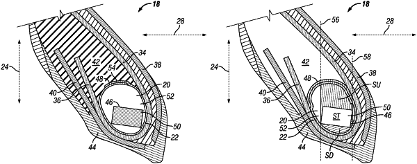
a casing that carries the tread, wherein the casing has a bead that has a bead core that has a rod with a perimeter, wherein the bead core has padding gum, wherein the bead has a contention armature that wraps around the bead core and that engages the padding gum, wherein the contention armature has an overlap that is free from engagement with the rod, wherein a majority of the overlap is located outward in the radial direction from the rod, wherein the contention armature engages itself along the overlap and wherein the rod engages the contention armature at a location inward in the radial direction from the overlap at a part of the contention armature that is not part of the overlap, wherein the overlap extends to a position that is outward in the axial direction from the entire rod;
wherein the bead has a bit outward journey that wraps around and engages a section of the contention armature and is a separate component from the contention armature, wherein the bit outward journey extends to an opposite bead in the casing;
wherein a first radial line extends in the radial direction and is located in the axial direction at an outermost point of the perimeter in the axial direction;
wherein a second radial line extends in the radial direction and is located in the axial direction at an innermost point of the perimeter in the axial direction;
wherein a first axial line extends in the axial direction and is located in the radial direction at an innermost point of the perimeter in the radial direction;
wherein a second axial line extends in the axial direction and is located in the radial direction at an outermost point of the perimeter in the radial direction;
wherein the perimeter of the rod defines an area ST;
wherein an outer area SU of the padding gum is the area of the padding gum located outward from the perimeter in the radial direction that is bounded by the first radial line and the second radial line and the contention armature;
wherein an inner area SD of the padding gum is the area of the padding gum located inward from the perimeter in the radial direction that is bounded by the first radial line and the second radial line and the contention armature;
wherein an axially outer area SO of the padding gum is the area of the padding gum located outward from the perimeter in the axial direction that is bounded by the first axial line and the second axial line and the contention armature;
wherein the axially inner area SI of the padding gum is the area of the padding gum located inward from the perimeter in the axial direction that is bounded by the first axial line and the second axial line and the contention armature;
wherein SU>=0.2 ST;
wherein SD>=0.2 ST;
wherein SO>=0.2 ST; and
wherein SI>=0.1 ST.
|