| CPC B60B 27/0068 (2013.01) [B60B 27/0005 (2013.01); B60B 27/0094 (2013.01); F16C 19/186 (2013.01); F16C 19/522 (2013.01); F16C 33/586 (2013.01); F16C 41/00 (2013.01); F16C 2233/00 (2013.01); F16C 2326/02 (2013.01)] | 7 Claims |
|
1. A sensorized wheel hub assembly for rotatably connecting a wheel with a shaft and a chassis, the hub assembly comprising:
an inner hub rotatable about a central axis and having opposing inboard and outboard axial ends, a radial flange extending outwardly from the outboard axial end and connectable with the wheel, an inner circumferential surface defining a central bore for receiving the shaft, and an opposing outer circumferential surface, the outer surface providing an inboard inner race and an outboard inner race spaced axially from the inboard inner race;
an outer hub disposed about the inner hub, connectable with the chassis and having inboard and outboard axial ends, an outer circumferential surface and an inner circumferential surface, the inner surface providing an inboard outer race and an outboard outer race spaced axially from the inboard outer race;
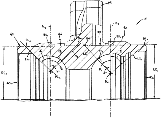
a first ball set of first rollers disposed between the inboard inner race and the inboard outer race and contacting the inboard outer race along a first circular contact path, the center of each first roller traversing a first pitch circle about the central axis, any line perpendicular to the contact path and extending between the contact path and the pitch circle defining a first angle (al) with respect to any radial plane through the central axis and intersecting the central axis at a first intersection point;
a second ball set of second rollers disposed between the outboard inner race and the outboard outer race and contacting the outboard outer race along a second circular contact path, the center of each second roller traversing a second pitch circle about the central axis, any line perpendicular to the second contact path and extending between the second contact path and the second pitch circle defining a second angle (α2) with respect to any radial plane through the central axis and intersecting the central axis at a second intersection point, the first and second intersection points being spaced apart by an axial distance (DA); and
at least one sensor configured to sense strain within the outer hub generated by one of the first and second ballsets;
wherein the outer hub has at least one exterior sensor mounting surface section located a radial spacing distance (RS) from the central axis, the at least one sensor being disposed on the mounting surface section, the radial spacing distance having a value less than a radial boundary distance (RB) defined as follows:
RS<RB=[DA×sin(90°−α1)×sin(90°−α2)]/sin(α1+α2)
wherein the at least one exterior senor mounting surface of the outer hub includes one of first and second axially spaced continuous circumferential sensor mounting surface sections, first and second axially spaced sets of a plurality of circumferentially spaced arcuate mounting surface sections, and one continuous circumferential mounting surface and one set of a plurality of circumferential spaced arcuate mounting surface sections, and the at least one sensor includes first and second sets of the sensors, each sensor of the first set of sensors being disposed on one of the first continuous circumferential surface section, the first set of circumferentially spaced arcuate mounting surface sections and the one continuous circumferential mounting surface section, each sensor of the second set of sensors being disposed on one of the second continuous circumferential mounting surface, the second set of circumferentially spaced arcuate mounting surface sections, and the one set of circumferentially spaced arcuate mounting surface sections;
wherein the first continuous circumferential sensor mounting surface section or the first set of arcuate mounting surface sections is located axially between first and second circumferential boundary lines on a first cylindrical boundary surface having a diameter of twice the radial spacing distance, the first circumferential boundary line being defined as the intersection of the cylindrical boundary surface by any straight line extending from the pitch circle in a direction toward the outer hub outboard axial end, forming an angle with respect to any plane perpendicular to the central axis having a value of fifteen degrees greater than the first contact angle, and revolved about the central axis, and the second circumferential boundary line being defined as the intersection of the cylindrical boundary surface by any straight line extending from the pitch circle in a direction toward the outer hub inboard axial end, forming an angle with respect to any plane perpendicular to the central axis having a value of forty degrees, and revolved about the central axis; and
wherein the second continuous circumferential sensor mounting surface section or the second set of arcuate mounting surface sections is located axially between third and fourth circumferential boundary lines on a second cylindrical boundary surface having a diameter of twice the radial spacing distance, the third circumferential boundary line being defined as the intersection of the cylindrical boundary surface by any straight line extending from the pitch circle in a direction toward the outer hub inboard axial end, forming an angle with respect to any plane perpendicular to the central axis having a value of fifteen degrees greater than the second contact angle, and revolved about the central axis and the fourth circumferential boundary line being defined as the intersection of the cylindrical boundary surface by any straight line extending from the pitch circle in a direction toward the outer hub outboard axial end, forming an angle with respect to any plane perpendicular to the central axis having a value of forty degrees, and revolved about the central axis.
|