| CPC B21B 37/68 (2013.01) [B21B 39/082 (2013.01); C21D 8/1222 (2013.01); C21D 9/562 (2013.01); B21B 2273/04 (2013.01); C21D 6/008 (2013.01)] | 12 Claims |

|
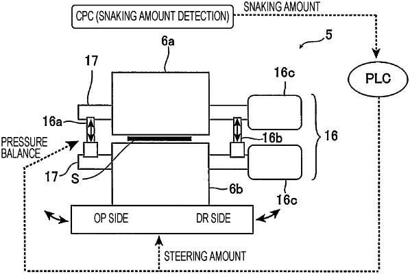
1. A bridle device comprising:
a pair of upper and lower rotatable endless belts or rotatable caterpillars configured to pinch a steel strip; and
a rolling reduction mechanism comprising hydraulic cylinders provided on both sides in the steel strip width direction, the rolling reduction mechanism configured to apply pressure to both sides of the steel strip via the pair of upper and lower rotatable endless belts or rotatable caterpillars,
wherein the bridle device is configured to move or swing in a steel strip width direction based on a steering amount of the bridle device,
the rolling reduction mechanism is configured to control rolling reduction on a pinched portion of the steel strip with a pressure balance among the hydraulic cylinders by increasing a pressure of the hydraulic cylinder provided on one of the sides of the steel strip, and
the steering amount of the bridle device and the pressure balance among the hydraulic cylinders are determined in accordance with a snaking amount of the steel strip.
|