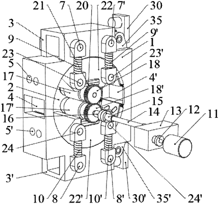
| CPC B21B 13/02 (2013.01) | 1 Claim |

|
1. A roller machine for a metal polar plate, comprising:
a box body;
a main transmission device;
a pressing adjustment structure;
an upper pressing roller; and
a lower pressing roller;
wherein the box body is a square, and a circular through hole is provided on a front surface of the box body;
an upper lug boss is provided at an upper end of the box body, and a lower lug boss is provided at a lower end of the box body;
a feed inlet is provided in a middle of a left side surface of the box body, and a discharge port is provided in a middle of a right side surface of the box body;
holes for upper and lower fixing screws are provided on an upper part and a lower part of the box body;
an upper left cantilever beam and an upper right cantilever beam are provided on a front surface of the upper lug boss; and a lower left cantilever beam and a lower right cantilever beam are provided on the lower lug boss;
the upper left cantilever beam is inserted into an upper left spring body; the upper right cantilever beam is inserted into an upper right spring body; the lower left cantilever beam is inserted into a lower left spring body; and the lower right cantilever beam is inserted into a lower right spring body;
the main transmission device comprises a servo motor, a safety coupling, a reduction gearbox, a transmission shaft, a cross coupling, a spline housing, and a synchronous gear; and the servo motor is connected to the synchronous gear at a shaft end of the lower pressing roller via the safety coupling, the reduction gearbox, the transmission shaft, the cross coupling and the spline housing;
the pressing adjustment structure comprises a servo electric cylinder, a connecting rod, an upper rotating block and a lower rotating block; and the pressing adjustment structure connected to the main transmission device is mounted in the circular through hole formed in the box body; and the upper rotating block and lower rotating block are sector-shaped;
a left bearing mounted on the upper pressing roller is mounted in a groove of the upper rotating block through a left bearing seat and a left bearing seat fixing plate; and a right bearing mounted on the lower pressing rollers is mounted in a groove of the lower rotating block through a right bearing seat and a right bearing seat fixing plate;
pressure sensors are arranged at the groove of the upper rotating block and the groove of the lower rotating block;
a supporting seat ring is provided at an arch-shaped top end of the upper rotating block; a pin shaft hole is provided in a center of the supporting seat ring and is hinged to a first end of the connecting rod through a pin shaft; a second end of the connecting rod is connected to the servo electric cylinder supported on a rotating sleeve; and the servo electric cylinder is mounted in a supporting seat through the rotating sleeve, and the supporting seat is fixedly mounted on a step of the box body;
a left rotating block supporting beam and a right rotating block supporting beam are provided on a front surface of the upper rotating block; the left rotating block supporting beam is inserted into a round hole provided on a lower end of the upper left spring body; and the right rotating block supporting beam is inserted into a round hole provided on a lower end of the upper right spring body;
a left arch-shaped plate is mounted at a left part of a surface of the circular through hole of the box body between the upper and lower rotating blocks by a left fixing screw; and a right arch-shaped plate is mounted at a right part of the surface of the circular through hole of the box body between the upper and lower rotating blocks by a right fixing screw; and
an adjustment bolt used for adjusting a position of the left arch-shaped plate is mounted in an adjustment bolt hole formed in the box body; threads at a first end of the adjustment bolt are engaged with threads on a side of the left arch-shaped plate; and the adjustment bolt is rotatable to drive the left arch-shaped plate to move.
|