| CPC A61B 18/082 (2013.01) [A61B 18/08 (2013.01); A61B 18/1492 (2013.01); A61B 18/24 (2013.01); A61B 18/20 (2013.01); A61B 90/39 (2016.02); A61B 2017/00026 (2013.01); A61B 2017/00084 (2013.01); A61B 2017/00119 (2013.01); A61B 2017/00123 (2013.01); A61B 2017/00132 (2013.01); A61B 2018/00636 (2013.01); A61B 2018/00666 (2013.01); A61B 2018/00779 (2013.01); A61B 2018/00791 (2013.01); A61B 2018/00827 (2013.01); A61B 2018/046 (2013.01); A61B 2090/0811 (2016.02); A61B 2090/3925 (2016.02); A61B 2090/3937 (2016.02); A61B 2090/3945 (2016.02)] | 19 Claims |

|
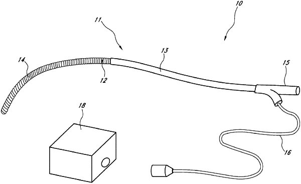
1. A catheter comprising:
a flexible elongated shaft having a distal end and a proximal end;
a resistive heating element located proximate the distal end of the shaft, the resistive heating element comprising a plurality of sections configured to be separately activated to adjust an active length of the resistive heating element between at least a first active length and a second active length greater than the first active length; and
a plurality of index markers located along the shaft and proximal of the resistive heating element,
wherein consecutive index markers of the plurality of index markers are spaced apart by a first distance that is less than the first active length,
wherein a second distance from a distal-most edge of a distal-most index marker of the plurality of index markers to a proximal-most edge of a proximal-most index marker of the plurality of index markers is less than the second active length of the resistive heating element, and
wherein each of the first active length, the second active length, the first distance, and the second distance is measured along a longitudinal axis of the shaft.
|