| CPC H02M 3/335 (2013.01) [H02M 3/01 (2021.05); H02M 7/4833 (2021.05); H02M 7/4835 (2021.05)] | 18 Claims |

|
1. A bridge circuit with series-connected switches, comprising:
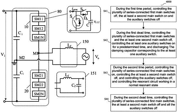
a first bridge arm, comprising a first terminal, a second terminal and a control terminal, wherein a plurality of series-connected first main switches are coupled between the first terminal and the second terminal, each of the plurality of series-connected first main switches is coupled in parallel with a first auxiliary module, each first auxiliary module comprises a first clamping capacitor and a first auxiliary switch, and the control terminal is configured to receive a first main switch signal to control the plurality of series-connected first main switches;
a second bridge arm, comprising a first terminal, a second terminal, a control terminal and at least a second main switch, wherein the first terminal of the second bridge arm is coupled with the second terminal of the first bridge arm at a common node, and the control terminal of the second bridge arm is configured to receive a second main switch signal to control the at least a second main switch;
a voltage sensing circuit, configured to sample voltages of the first clamping capacitors in the first bridge arm, and configured to correspondingly generate first voltage sensing signals according to the voltages of the first clamping capacitors; and
a control circuit, configured to receive the first voltage sensing signals and correspondingly generate first auxiliary switch signals according to the first voltage sensing signals and a first dead time to respectively control the first auxiliary switches,
wherein when a certain first voltage sensing signal ranks at top M among the first voltage sensing signals, the control circuit is configured to control the first auxiliary switch corresponding to the certain first voltage sensing signal keeping on for a first predetermined time during the first dead time, wherein the first predetermined time is less than or equal to the first dead time, and M is a natural number greater than or equal to one, and
wherein the common node is configured to output an output current and an output voltage, a working cycle comprises the first dead time and a second dead time, during the working cycle, when the output current is configured to lag behind the output voltage, the first dead time is before a rising edge of the first main switch signal, the second dead time is before a rising edge of the second main switch signal, when the output current is configured to lead the output voltage, the first dead time is before a rising edge of the second main switch signal, the second dead time is before a rising edge of the first main switch signal.
|