| CPC H02H 3/207 (2013.01) [H02H 1/0007 (2013.01)] | 12 Claims |

|
1. An electronic protection circuit comprising:
a supply terminal operative to receive a supply current;
a common terminal operative to return at least a part of the supply current;
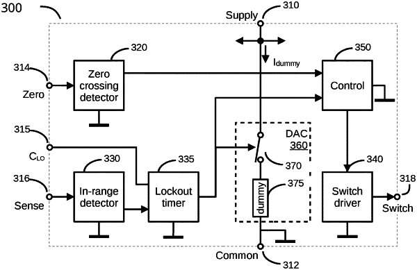
a sense terminal electrically coupled with a range detector, wherein the range detector is operative to determine whether a peak value of an external raw supply voltage is inside an allowed range, wherein the allowed range may be widened in a first state and narrowed in a second state, and wherein the range detector delivers a range-detection output signal that signals an in-range condition or an out-of-range condition dependent on the peak value of the external raw supply voltage being inside the allowed range;
one or more zero-crossing detection input terminals electrically coupled with a zero-crossing detector, wherein the zero-crossing detector is operative to determine a time of a first zero crossing and a time of a second zero crossing, wherein the time of the first zero crossing is a time of a zero crossing detected after the range-detection output signal has signaled an in-range condition and the time of the second zero crossing is a time of a zero crossing detected after the range-detection output signal has signaled an out-of-range condition;
a switch driver output terminal coupled with a switch driver output;
a control unit with a first input coupled with an output of the zero-crossing detector, a second input coupled with the output of the range detector, and an output coupled with an input of a switch driver, wherein the control unit is configured to change the switch driver to an on state starting from the time of the first zero crossing until the time of the second zero crossing; and
a dummy digital-to-analog converter (DAC) with current output operative to supply a dummy current that prevents instability resulting from positive feedback during a change from the first state to the second state and during a change from the second state to the first state, wherein the dummy current flows from the supply terminal through the dummy DAC to the common terminal.
|
|
11. A method for protecting a load from overvoltage or undervoltage conditions in a raw supply voltage between a line rail and a neutral rail, comprising:
(a) from a protection integrated circuit (IC), providing a first switch signal to a switch to decouple the load from the raw supply voltage, wherein the switch is coupled between the load and one of the line rail and the neutral rail;
(b) in the protection IC, initializing a dummy current to a first value;
(c) providing a raw supply voltage sense signal to the protection IC, and in the protection IC, determining if a peak value of the raw supply voltage is in a narrowed allowed range by comparing the raw supply voltage sense signal with first window threshold values;
(d) upon determining that the peak value of the raw supply voltage is not in the narrowed allowed range, returning to step (c);
(e) upon determining that the peak value of the raw supply voltage between the line rail and the neutral rail is in the narrowed allowed range, widening the narrowed allowed range to a widened allowed range, delimited by second window threshold values;
(f) waiting for a first zero crossing in a zero-crossing detector input signal of the protection IC;
(g) changing the dummy current to a second value;
(h) from the protection IC, providing a second switch signal to the switch to couple the load with the raw supply voltage;
(i) in the protection IC, determining if the peak value of the raw supply voltage is outside the widened allowed range by comparing the raw supply voltage sense signal with the second window threshold values;
(j) upon determining that the peak value of the raw supply voltage is not outside the widened allowed range, returning to step (i);
(k) upon determining that the peak value of the raw supply voltage is outside the widened allowed range, narrowing the widened allowed range to the narrowed allowed range;
(l) waiting for a second zero crossing;
(m) changing the dummy current to a third value; and
(n) providing the first switch signal to the switch to decouple the load from the raw supply voltage.
|