| CPC G01N 1/44 (2013.01) [G01N 1/28 (2013.01); F01N 3/021 (2013.01); G01N 15/02 (2013.01); G01N 15/06 (2013.01); G01N 15/1012 (2013.01); G01N 2001/2893 (2013.01)] | 15 Claims |

|
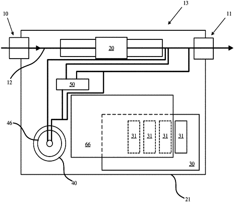
1. An apparatus for generating reference particulate (particulate matter (PM)/particle number (PN)) and creating conditions for a PM/PN simulation and/or facsimile event, comprising:
a housing having an inlet and an outlet;
a filter configured to remove of a specific diameter of particulates;
a sealed tank reservoir in the housing;
a removable liquid exhaust tank mounted in the sealed tank reservoir, the liquid exhaust tank configured to contain a fluid;
a heating element mounted within the sealed tank reservoir, wherein the heating element is configured to provide a variable fluid vaporization rate, and wherein the heating element is configured to atomize the fluid;
one or more sensors to measure at least one of pressure, flow, temperature, or humidity; and
four flow control valves along a flow path between the inlet and the outlet, wherein a first flow control valve is disposed between the inlet and the outlet, wherein a second flow control valve is disposed between the inlet and the filter, wherein a third flow control valve is disposed between the sealed tank reservoir and the filter, and wherein a fourth flow control valve is disposed between the sealed tank reservoir and the outlet.
|