| CPC G01B 9/0201 (2013.01) [G01P 3/363 (2013.01); G02F 1/11 (2013.01); G02F 2/00 (2013.01); H01S 5/0085 (2013.01)] | 19 Claims |

|
1. A laser interferometer comprising:
a light source that emits first laser light;
an optical modulator that includes a vibrator and modulates the first laser light by using the vibrator to generate second laser light including a modulated signal;
a photodetector that receives interference light between third laser light including a sample signal generated by reflecting the first laser light on an object and the second laser light to output a light reception signal;
a demodulation circuit that demodulates the sample signal from the light reception signal based on a reference signal; and
a signal generator that outputs the reference signal input to the demodulation circuit and outputs a drive signal input to the optical modulator, wherein
Vd/Vr<10, where Vr is a voltage of the reference signal and Vd is a voltage of the drive signal,
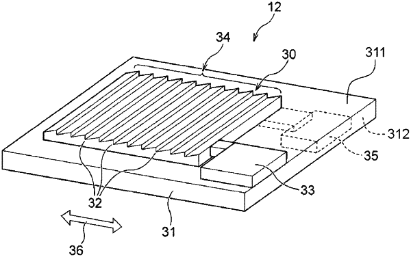
the vibrator has a crystal AT resonator, and the crystal AT resonator is configured to vibrate by thickness sliding along a vibration direction,
a diffraction grating is formed on a surface of the crystal AT resonator, and the diffraction grating is configured with a plurality of grooves,
the second laser light is formed by modulating the first laser light at the plurality of grooves, and
an extending direction of each of the plurality of grooves is perpendicular to the vibration direction.
|