| CPC F16K 31/043 (2013.01) [F16K 5/0605 (2013.01); F16K 27/067 (2013.01)] | 20 Claims |

|
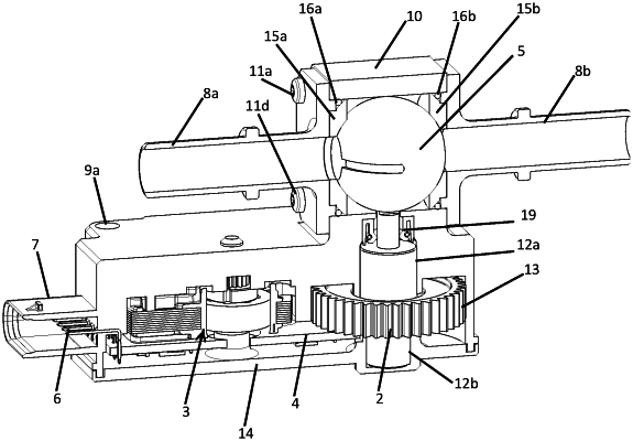
1. A motorised valve comprising:
a body with at least one intake duct and one outlet duct;
a plug movably mounted in the body to plug or release a passage between the intake duct and the outlet duct; and
a motorised control system operably controlling movement of the plug, the motorised control system comprising a gear motor comprising an electric motor and a reduction gear train, the reduction gear train comprising one or more gears and an exit wheel, the exit wheel configured to rotate the plug of the valve so as to allow progressive opening of the valve, the electric motor having a motor rotational axis, the exit wheel having an exit wheel rotational axis, and each of the one or more gears having a gear rotational axis, the exit wheel rotational axis and each gear rotational axis parallel to the motor rotational axis;
the gear motor being a casing comprising the electric motor and the reduction gear train, the body being integrally formed with the casing without a mounting brace therebetween;
the casing defining an inner space therein, said inner space having the electric motor and the reduction gear train disposed therein, wherein the electric motor and exit wheel are located in the inner space along a plane which runs perpendicular to the exit wheel rotational axis.
|