| CPC F02C 7/18 (2013.01) [F01D 1/026 (2013.01); F01D 15/10 (2013.01); F01D 25/12 (2013.01); F02C 6/06 (2013.01); F05D 2260/211 (2013.01)] | 20 Claims |

|
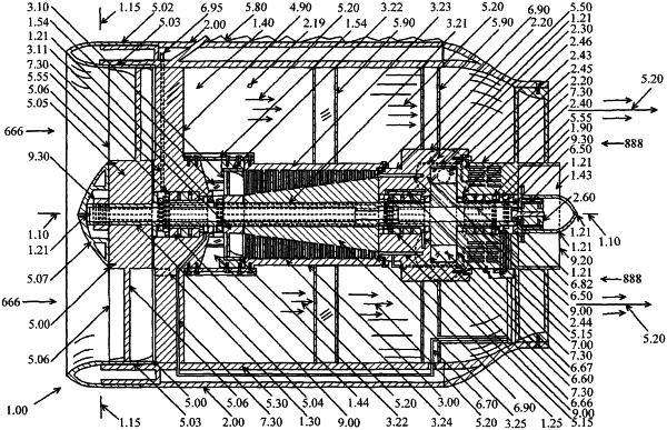
1. A gas-wind turbine engine using air cooling, the engine comprising:
a gas-wind turbine engine housing extending longitudinally between a first end and a second end of the gas-wind turbine engine housing, the gas-wind turbine engine housing defining a rotor cavity bounded at longitudinally opposing ends by a first wall and a second wall of the rotor cavity respectively and bounded peripherally by a third wall extending longitudinally between the first wall and the second wall;
a gas-wind turbine engine rotor having a plurality of gas-wind turbine engine rotor blades supported within the rotor cavity of the gas-wind turbine engine housing such that the gas-wind turbine engine rotor is rotatable about a rotor axis oriented longitudinally of the gas-wind turbine engine housing;
the gas-wind turbine engine housing including a first housing gap in communication with the rotor cavity through the first wall of the rotor cavity and a second housing gap in communication with the rotor cavity through the second wall of the rotor cavity;
an air compressor powered by rotation of the gas-wind turbine engine rotor to generate a pressurized air flow;
a combustor receiving fuel from a fuel system and receiving the pressurized air flow from the air compressor, the combustor being arranged to combust a fuel and air mixture from the fuel system and the air compressor respectively to generate an exhaust gas flow;
the combustor including an exhaust duct arranged to direct the exhaust gas flow from the combustor into the rotor cavity, the exhaust duct being separate from the first housing gap and the second housing gap of the gas-wind turbine engine housing, and the exhaust duct being directed into the rotor cavity circumferentially of the gas-wind turbine engine rotor;
a mixture flow duct at the second end of the gas-wind turbine engine housing, the mixture flow duct being in communication with the rotor cavity through the second wall of the rotor cavity whereby the mixture flow duct is arranged to receive the exhaust gas flow discharged from the gas-wind turbine engine rotor rotating within the gas-wind turbine engine housing;
a cooling fan at the first end of the gas-wind turbine engine housing, the cooling fan being operatively connected to the gas-wind turbine engine rotor so as to be driven to rotate by rotation of the gas-wind turbine engine rotor whereby the cooling fan generates a cooling fan air flow longitudinally of the gas-wind turbine engine housing;
the cooling fan being in communication with the first housing gap in the first wall of the rotor cavity such that at least a portion of the cooling fan air flow is directed through the rotor cavity from the first housing gap in the first wall to the second housing gap in the second wall whereby (i) the cooling fan air flow partly drives rotation of the gas-wind turbine engine rotor about the rotor axis and (ii) cools the gas-wind turbine engine rotor blades;
the second housing gap in the second wall of the rotor cavity communicating with the mixture flow duct whereby the mixture flow duct receives said at least a portion of the cooling fan air flow together with the exhaust gas flow discharged from the gas-wind turbine engine rotor rotating within the gas-wind turbine engine housing.
|