| CPC F01P 1/06 (2013.01) [F01P 5/04 (2013.01); F01P 2005/025 (2013.01)] | 21 Claims |

|
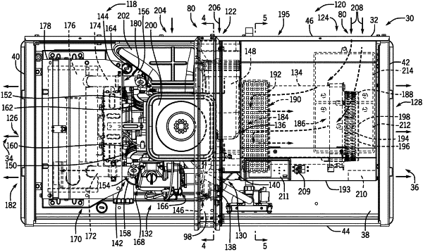
1. A standby generator comprising:
a standby generator enclosure having a first end and a second end opposite the first end, the standby generator enclosure comprising:
a partition wall separating the first end from the second end,
one or more airflow openings, and
a first air duct and a second air duct each coupled to at least one of the one or more airflow openings;
an engine mounted in the enclosure toward the first end from the partition wall, the engine comprising an engine cooling fan fluidly coupled to the first air duct; and
an alternator driven by the engine and mounted in the enclosure toward the second end from the partition wall, the alternator comprising an alternator cooling fan fluidly coupled to the second air duct;
wherein the engine cooling fan faces the first end to drive engine cooling air received from the first air duct toward the first end, and the alternator cooling fan faces the second end to drive alternator cooling air received from the second air duct toward the second end.
|