| CPC E21B 23/001 (2020.05) [E21B 17/073 (2013.01); E21B 23/042 (2020.05); E21B 23/0411 (2020.05); E21B 23/0412 (2020.05); E21B 43/263 (2013.01)] | 8 Claims |

|
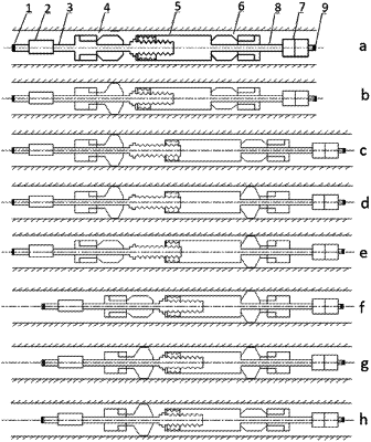
1. A downhole explosion robot based on planetary roller screw telescoping, comprising a rear joint (1), a rear main body (3), a telescopic sub (5), a front main body (8), and a front joint (9) connected in sequence from left to right, the rear main body (3) and the front main body (8) are provided with axial through-holes, and the rear main body (3) is provided with a rear control sub (2) and a rear support sub (4); the front main body (8) is provided with a front support sub (6) and a front control sub (7), and the telescopic sub (5) is respectively connected with the rear support sub (4) and the front support sub (6), wherein the front support sub (6), the front control sub (7), the front main body (8) and the front joint (9) are respectively distributed symmetrically with the rear support sub (4), the rear control sub (2), the rear main body (3) and the rear joint (1) with respect to the telescopic sub (5); the rear control sub (2) controls the rear support sub (4) to enter support state or non-support state, and the front control sub (7) controls the front support sub (6) to enter support state or non-support state;
the rear support sub (4) comprises a rear support cylinder (402), a rear support cylinder flange (401), a rear support cylinder piston (403), and a rear support mechanism, the rear support cylinder flange (401) is connected with a left end of the rear support cylinder (402), and the rear support cylinder piston (403) is sleeved in a middle of the rear support cylinder (402) and the rear main body (3), and can slide relatively;
the rear support mechanism comprises a rear support rear sliding seat (404), a rear support rear arm (405), a rear support rear link, a rear support block (406), a rear support front arm (407), a rear support front link, and a rear support front sliding seat (408);
a left end of the rear support rear arm (405) is rotatably connected with a left end of the rear support rear sliding seat (404), and left and right ends of the rear support block (406) are respectively rotatably connected with a right end of the rear support rear arm (405) and a left end of the rear support front arm (407), a right end of the rear support front arm (407) is rotatably connected to a right end of the rear support front sliding seat (408), left and right ends of the rear support rear link are respectively rotatably connected to a right end of the rear support rear sliding seat (404) and a middle of the rear support block (406), and left and right ends of the rear support front link are respectively rotatably connected with the middle of the rear support block (406) and a left end of the rear support front sliding seat (408);
the rear support cylinder flange (401) and the rear support front sliding seat (408) are threadedly connected with the rear main body (3) to limit a relative position of the rear support sub (4); the rear support rear sliding seat (404) is connected with a protruding portion of the rear support cylinder piston (403);
the telescopic sub (5) comprises a telescopic protective cover (501), a motor fixing frame (503), a drive motor (504), a bearing (505) and a planetary roller screw mechanism slidably installed in the telescopic protective cover (501); the planetary roller screw mechanism comprises a plurality of planetary rollers (507), a nut (510), and a lead screw (511);
the motor fixing frame (503) and the bearing (505) are installed in a left end of the telescopic protective cover (501), the drive motor (504) is installed on the motor fixing frame (503), the telescopic protective cover (501) is internally provided with a limit rail (502), and the nut (510) is slidably installed in the limit rail (502);
both ends of each of the plurality of the planetary rollers (507) are provided with a gear teeth (506) and a cage (508) in sequence from an inside to an outside, each of the plurality of the planetary rollers (507) is threadedly installed in the nut (510), and the nut (510) is internally provided with a snap ring (509) for limiting the plurality of the planetary rollers (507) at a left end of an inner chamber of the nut (510); and
the lead screw (511) is installed in the bearing (505) and the plurality of the planetary rollers (507), and a rotating shaft of the drive motor (504) is connected with the lead screw (511) through a coupling; the telescopic protective cover (501) is connected with the rear support front sliding seat (408).
|