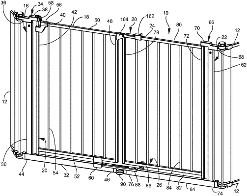
| CPC E06B 11/022 (2013.01) [E04H 17/1439 (2013.01)] | 5 Claims |

|
1. A double door gate apparatus, comprising:
a) a first base frame, the first base frame including a first outer end frame member that extends vertically and a first lowermost frame member that extends horizontally, the first lowermost frame member having a first inner end, the first inner end having a top face, front face, and rear face;
b) a first gate engaged to the first base frame;
c) a second base frame, the second base frame including a second outer end frame member that extends vertically and a second lowermost frame member that extends horizontally, the second lowermost frame member having a second inner end, the second inner end having a top face, front face and rear face;
d) a second gate engaged to the second base frame;
e) a first connector engaging the first inner end of the first lowermost frame member to the second inner end of the second lowermost frame member, the first connector comprising an elongate rigid brace, the elongate rigid brace being integral and one-piece, the elongate rigid brace having a first U-shaped section that engages the top, front and rear faces of the first inner end, the elongate rigid brace having a second U-shaped section that engages the top, front and rear faces of the second inner end, the first and second base frames being nonpivotable relative to each other when the elongate rigid brace is engaged to the first and second inner ends of the first and second lowermost frame members; and
f) a second connector engaging the first inner end of the first lowermost frame member to the second inner end of the second lowermost frame member, wherein the first inner end of the first lowermost frame member is tubular and includes a first opening, wherein the second inner end of the second lowermost frame member is tubular and includes a second opening, and wherein the second connector comprises an elongate insert having first and second insert ends, the first insert end being engagable with the first opening, the second insert end being engagable with the second opening.
|