US 11,667,348 B2
Bicycle with battery, motor and motor mount, wire routing, speed sensor, and dropper seat post
Marc Pallure, Zug (CH); Marco Werner Sonderegger, Benzenschwil (CH); Jan Talavasek, Knonau (CH); and Vincent Patureau, Zurich (CH)
Assigned to SPECIALIZED BICYCLE COMPONENTS, INC., Morgan Hill, CA (US)
Appl. No. 17/269,597
Filed by Specialized Bicycle Components, Inc., Morgan Hill, CA (US)
PCT Filed Aug. 21, 2019, PCT No. PCT/US2019/047435
§ 371(c)(1), (2) Date Feb. 19, 2021,
PCT Pub. No. WO2020/041425, PCT Pub. Date Feb. 27, 2020.
Application 17/269,597 is a continuation of application No. 16/107,693, filed on Aug. 21, 2018, granted, now 10,906,610, issued on Feb. 2, 2021.
Application 16/107,693 is a continuation of application No. 16/107,701, filed on Aug. 21, 2018, granted, now 11,046,389.
Application 16/107,701 is a continuation of application No. 16/107,710, filed on Aug. 21, 2018, granted, now 10,906,609, issued on Feb. 2, 2021.
Application 16/107,710 is a continuation of application No. 16/107,715, filed on Aug. 21, 2018, granted, now 11,124,259.
Application 16/107,715 is a continuation of application No. 16/107,706, filed on Aug. 21, 2018, granted, now 11,117,634.
Claims priority of provisional application 62/720,729, filed on Aug. 21, 2018.
Prior Publication US 2021/0197927 A1, Jul. 1, 2021
This patent is subject to a terminal disclaimer.
Int. Cl. B62M 6/90 (2010.01); B62K 3/02 (2006.01); B62M 6/40 (2010.01); B62M 6/55 (2010.01); B62J 11/19 (2020.01)
CPC B62M 6/90 (2013.01) [B62K 3/02 (2013.01); B62M 6/40 (2013.01); B62M 6/55 (2013.01); B62J 11/19 (2020.02)] 21 Claims
OG exemplary drawing
 
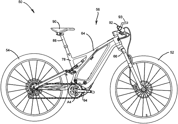
1. A bicycle comprising:
a front wheel;
a rear wheel;
a frame structure supported on the front wheel and the rear wheel, the frame structure including a top tube, a hollow seat tube, and a bottom shell positioned below the hollow seat tube, the bottom shell having an inner surface;
a dropper seat post supported by the hollow seat tube;
a loop stay positioned in the frame structure below the dropper seat post; and
a control housing positioned in the frame structure, wherein the control housing is coupled to the dropper seat post and is coupled to the loop stay;
wherein the loop stay is positioned below the top tube and relative to the inner surface of the bottom shell such that the control housing cannot pass between the loop stay and the inner surface of the bottom shell.