| CPC B60C 11/11 (2013.01) [B60C 11/1204 (2013.01); B60C 11/1236 (2013.01); B60C 2200/14 (2013.01)] | 10 Claims |

|
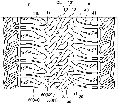
1. A pneumatic tire, comprising:
a tread portion extending in a tire circumferential direction and having an annular shape;
a pair of sidewall portions disposed on opposite sides of the tread portion; and
a pair of bead portions disposed inward of the sidewall portions in a tire radial direction, wherein
a plurality of center blocks are provided in a center region of the tread portion and a plurality of shoulder blocks are provided in shoulder regions of the tread portion,
the center blocks are arranged forming a pair sandwiching an inclined groove that extends inclined with respect to the tire circumferential direction,
one of the pair of the center blocks extends across a tire equator from one side to another side of the tire equator and another of the pair of the center blocks extends across the tire equator from the other side to the one side of the tire equator,
each of the center blocks includes a notch formed of two wall surfaces connected in a V-shape in a tread road contact surface, only a singular bend point being present between the two wall surfaces and being where the two wall surfaces are connected,
the two wall surfaces include, in the tread contact surface, a first wall that extends at an angle within +/−20° with respect to the tire circumferential direction and a second wall that extends at an angle within +/−10° with respect to a tire lateral direction,
each of the shoulder blocks includes a third wall disposed opposed to the notch of the center block, and
the third wall extends at an angle within +/−5° with respect to a straight line connecting an end point P1 of the first wall, which is located adjacent to the shoulder block and an end point P2 of the second wall, which is located adjacent to the shoulder block.
|