| CPC B09B 3/60 (2022.01) [A22B 7/008 (2013.01); B09B 3/35 (2022.01); B09B 3/38 (2022.01); B09B 2101/70 (2022.01)] | 9 Claims |

|
1. An enzymatic hydrolysis device for livestock and poultry slaughter by-products, comprising:
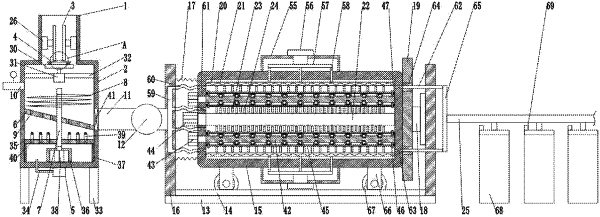
a liquid injection crushing mechanism, wherein the liquid injection crushing mechanism comprises a feeding barrel, a crushing box is fixed and communicated with a bottom end of the feeding barrel; two symmetrically arranged rolling plates are arranged in the feeding barrel, and a rolling space is arranged between the two rolling plates; a bottom of the rolling space is provided with a bearing plate, and the bearing plate is movably arranged at a joint of the feeding barrel and the crushing box; an air pump is fixed at a bottom of the crushing box, and an output end of the air pump is communicated with the crushing box; a first partition is fixed in the crushing box, a rotating rod penetrates through a center of the first partition, and the rotating rod is rotatably connected with the first partition; a spiral blade is fixed at a part of the rotating rod at a top of the first partition, a plurality of through holes are formed through the first partition, and waterproof breathable films are embedded in the through holes; any side wall of the crushing box is fixedly connected with a liquid injection pipe, and the side wall of the crushing box opposite to the liquid injection pipe is fixedly connected and communicated with a first discharge pipe; both the first discharge pipe and the liquid injection pipe are located at the top of the first partition, and a booster pump is installed on the first discharge pipe;
a mixing disturbance mechanism, wherein the mixing disturbance mechanism comprises a bottom plate, a slide rail fixed on a top surface of the bottom plate, a tank body slidably connected to the slide rail, baffles fixed at both ends of the bottom plate, a plurality of support springs fixedly connected between any baffle and the tank body, a first telescopic cylinder fixed to the other baffle, and a push plate fixed at an output end of the first telescopic cylinder; the push plate is fixedly connected with one end of the tank body farther away from the support springs; the tank body is internally provided with a plurality of circumferentially distributed curved panels, and the curved panels are embedded with the heating wires; the curved panels abut each other, and a disturbance space is enclosed among the curved panels; there are a plurality of circumferentially distributed disturbance components in the disturbance space, and a central shaft is arranged among the disturbance components; the disturbance components comprise a plurality of first stirring blades, and a plurality of second stirring blades are fixed on a surface of the central shaft, and each second stirring blade is located between two adjacent first stirring blades; the first discharge pipe is communicated with one end of the disturbance space, and the other end of the disturbance space is communicated with a second discharge pipe; and
a material collecting mechanism, wherein the material collecting mechanism is used for receiving materials sent by the second discharge pipe; and
the disturbance components comprise inner rods; one end of each inner rod is fixedly connected with an output shaft of each second motor, and an other end of each inner rod is axially connected with the tank body; one end of the central shaft is fixedly connected with an output shaft of a third motor, and an other end of the central shaft is axially connected with the tank body; the second motors and the third motor are fixed on an outer side of the tank body; each outer cylinder is sleeved on an outer side of each inner rod, and the plurality of first stirring blades are fixed on an outer side of each outer cylinder; two ends of each inner rod are pierced with annular plates, one end of each annular plate abuts against an end face of each outer cylinder, and a plurality of damping springs are fixed between an other end of each annular plate and an end face of the tank body; a plurality of cylinders are fixed on an inner side of each outer cylinder, and limiting columns are slidably connected in the cylinders; each limiting spring is fixed between one end of each limiting column and each cylinder, and each spherical protrusion is fixed on an other end of each limiting column; a surface of each inner rod is provided with a plurality of limiting grooves, and magnet blocks are fixed in the limiting grooves; the spherical protrusions extend into the limiting grooves and attract with the magnet blocks; two ends of each limiting groove are respectively provided with a limiting plate, and each limiting plate is fixed on the surface of each inner rod.
|