| CPC A01B 63/114 (2013.01) [A01B 63/102 (2013.01); A01B 63/1112 (2013.01); A01B 63/28 (2013.01)] | 18 Claims |

|
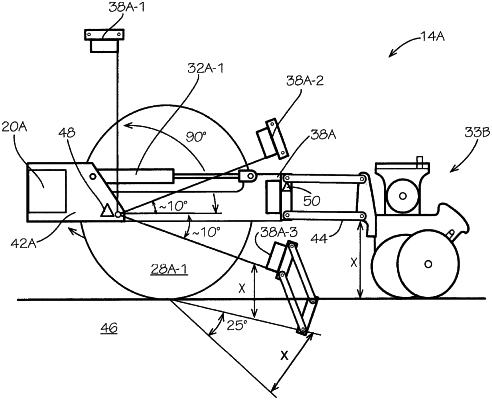
1. A system, comprising:
an elongate frame member;
an elongate toolbar coupled to the frame member via a hinged joint, the toolbar oriented parallel to the frame member;
a plurality of row units coupled to the toolbar;
a first sensor configured to sense a position of the toolbar relative to ground;
a second sensor configured to sense an angle of the toolbar relative to the frame member; and
an actuator coupled between the frame member and the toolbar, the actuator configured to rotate the toolbar relative to the frame member based on a sensed position of the toolbar, wherein the toolbar remains parallel to the frame member throughout the rotation of the toolbar.
|