|
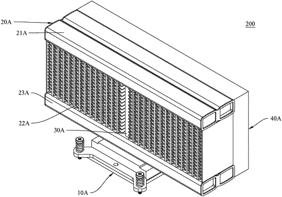
1. A stack-type vertical heat dissipation device, comprising: an evaporator unit having a side configured for direct or indirect contact with, and thereby receiving heat from, a high-temperature device in order for the heat to convert a heat conduction medium inside the evaporator unit into a gaseous state; and a condenser unit stacked on a top side of the evaporator unit, the condenser unit being provided therein with a flow channel, the flow channel being in communication with the evaporator unit and allowing passage of the heat conduction medium so that the heat conduction medium is able to return to the evaporator unit under a force of gravity after condensing from the gaseous state into a liquid state and thereby complete a thermal cycle; wherein the condenser unit comprises an upper main duct, a lower main duct, a plurality of flat tubes each having two opposite ends coupled to and communicating with the upper main duct and the lower main duct respectively, at least one main gas-flow passage tube that is coupled between and in communication with the upper main duct and the evaporation chamber, and a plurality of heat dissipation fins are provided around the flat tubes; wherein the evaporator unit includes a housing, an evaporation chamber provided inside the housing, and a skived structure provided in the evaporation chamber; wherein the main gas-flow passage tube has a lower-end opening, the lower-end opening of the main gas-flow passage tube is directly aligned above the skived structure, a main body extending through a middle portion of the lower main duct, and an upper-end opening of the main gas-flow passage tube is directly aligned above the lower-end opening of the main gas-flow passage tube and in communication with the upper main duct; wherein the main gas flow passage tube is vertical and goes straight in between the lower main duct and the upper main duct, the heat dissipation fins respectively are disposed on two opposite lateral sides of the main gas-flow passage tube, and the lower-end opening of the main gas-flow passage tube overlaps with the skived plates through a top view direction; wherein the skived structure includes a plurality of skived plates that are formed on the inner bottom side of the housing by skiving, a distance between each two adjacent skived plates ranges from 0.1 mm to 0.5 mm; and wherein a plurality of drainage tubes are provided between the lower main duct and the evaporator unit, each drainage tube of the plurality of drainage tubes has an upper-end opening in communication with an inner bottom side of the lower main duct and a lower-end opening in communication with an internal chamber of the evaporator unit, and the upper-end opening and the lower-end opening of each drainage tube of the plurality of drainage tubes are directly aligned such that the upper-end opening is above the lower-end opening, wherein the main gas-flow passage tube is located between the plurality of drainage tubes.
|
