| CPC H01S 5/022 (2013.01) [G02B 5/18 (2013.01); G02B 6/02209 (2013.01); G02B 6/34 (2013.01); G02B 6/42 (2013.01); G02B 6/4204 (2013.01); G02B 6/4214 (2013.01); H01S 5/023 (2021.01)] | 10 Claims |

|
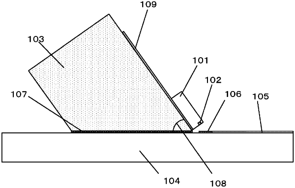
1. A mounting structure for an optical module, the mounting structure comprising:
a light emitting element;
a submount board having a first surface on which the light emitting element is mounted;
a main board on which the submount board is mounted;
a light guide member provided on the main board; and
a diffraction grating optical coupler provided on the main board and connected to the light guide member,
wherein a second surface of the submount board is fixed to the main board, the second surface being different from the first surface on which the light emitting element is mounted,
wherein an angle between a surface of the main board on which the diffraction grating optical coupler is mounted and the first surface of the submount board on which the light emitting element is mounted is 54.75°±5°, and
wherein an angle between the second surface of the submount board fixed to the main board and the first surface of the submount board on which the light emitting element is mounted is 54.75°±5°.
|