| CPC F28D 15/04 (2013.01) | 8 Claims |

|
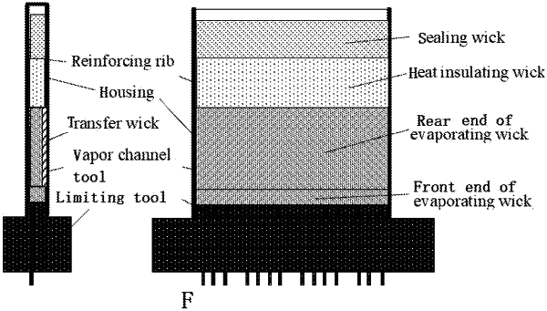
1. A positive-pressure-withstanding high-power flat evaporator, comprising a housing and a capillary wick arranged inside the housing (1), wherein one or more reinforcing ribs (2) are arranged inside the housing (1), and the reinforcing ribs (2) are positioned at the middle section of the housing (1) wherein the two ends of each reinforcing rib (2) in a length direction do not extend out of the housing (1);
the capillary wick is of a rectangular structure consistent with an inner cavity structure of the housing (1), and comprises an evaporating wick (3), a heat insulating wick (4) and a transfer wick (6); wherein the evaporating wick (3) is used for providing capillary force, and vapor channels (7) having the same length as the evaporating wick (3) are arranged on the end surface of one side of the evaporating wick (3);
wherein an air accumulation chamber is defined by a space formed by a gap between one end of the evaporating wick (3) in a length direction and the inner surface of the housing (1); and the other end of the evaporating wick (3) in the length direction is provided with the heat insulating wick (4) for blocking heat leakage from the evaporator to a reservoir;
wherein the transfer wick (6) is arranged on a surface of the evaporating wick (3) opposite to the surface on which the vapor channels (7) are positioned, and the transfer wick (6) is used for realizing low-flow-resistance liquid transfer from the reservoir to the evaporating wick (3); and the end of the transfer wick (6) proximal to the air accumulation chamber side does not penetrate through the evaporating wick (3) and is wrapped by the evaporating wick (3).
|